Difference Between CAD and CAM: Definition and Benefits
 Jan 18,2025

In modern manufacturing, Computer Aided Design (CAD) and Computer Aided Manufacturing (CAM) work together to form a fully automated and precise manufacturing system. Erroneously, some people interchange the two terms. But, they both serve different functions. We’ll be clarifying these misconceptions here.
What is CAD?
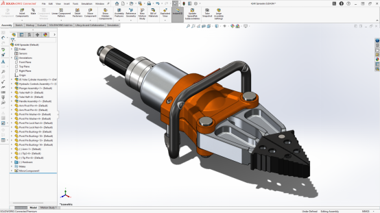
CAD is the use of computers to conceptualize, design, analyze and optimize designs. Although CAD is commonly abbreviated for Computer Aided Design, some industries abbreviate it for Computer Aided Drafting. It brings ease, flexibility, precision, accuracy and cost effectiveness in design and manufacturing processes.
2D vs 3D CAD: Key Differences
In engineering designs, both 2D drawings and 3D modellings are required. 2D drawings are akin to the blueprints that were painstakingly hand-drawn in early days. Now these are done with much ease and precision using a CAD. In contrast to 2D drawings, 3D models provide a real-world depiction of the CAD when rendered properly. They help a lot in visualization. It makes assembly and joining scheme for different components very easy. Engineers can optimize their designs effectively with the help of 3D models and dimensions can be communicated with ease using 2D drawings.
ECAD vs MCAD
ECAD is electronic CAD and MCAD is Mechanical CAD. While ECAD is used mainly for electrical applications like PCB layout or wiring diagrams, MCAD is used mainly for mechanical applications like product design or 3D models of a gear mechanism for instance. The below table highlights the key differences between them:
|
Feature |
MCAD |
ECAD |
|
Applications |
Mechanical applications like product design, machinery, automotive |
Electrical applications like circuit design, PCB layout |
|
Common Software |
SolidWorks, AutoCAD, CATIA, Inventor |
AutoCAD Electrical, OrCAD, Altium Designer |
|
Design Features |
3D models, assemblies, mechanical components |
Schematics, circuit boards, wiring diagrams |
|
Deliverables |
3D models, 2D drawings, Bill of material (BOM) |
Circuit diagrams, PCB layouts |
What is CAM?
CAM stands for Computer Aided Manufacturing. It is basically the use of a computer software to convert the CAD files to a machine-readable language. In short it is an intermediary between the CAD and the CNC machines. CAM performs certain processing over the CAD files to make them usable for CNCs.
Types of CAM Software and Their Functions
Different CAM software are being made for different specifications of CNC machines. Some companies who manufacture CNC machines like Siemens have developed their own CAM software. Generally, CAD and CAM exist as standalone software, but some, developers have combined both: Creo is an example. It is both CAD and CAM. Even if the CAD files have to exported to a separate CAM software, these must be compatible. Universally, .STEP and .IGES file formats are considered to be compatible with most CAM software. To further simplify the exporting issue, CAD software developers and CAM programmers have developed their own set of CAD and CAM software.
Some of the common CAM software are listed in the below table:
|
CAM Software |
Developer |
Key Features |
|
Mastercam |
CNC Software, Inc. |
Multi-axis machining, toolpath optimization |
|
SolidWorks CAM |
Dassault Systèmes |
Integrated with SolidWorks, rule-based machining |
|
Fusion 360 CAM |
Autodesk |
Cloud-based, multi-axis, additive manufacturing |
|
HSMWorks |
Autodesk |
Integrated with SolidWorks, adaptive toolpaths |
|
GibbsCAM |
3D Systems |
Multi-axis machining, high-speed machining |
LCAM vs CAM
LCAM stands for Lathe Computer Aided Manufacturing. Broadly speaking, LCAM comes under the same classification as CAM but there is little difference. LCAM is specifically designed for generating toolpaths for lathe machines. There are specialized LCAM software like GibbsCAM Lathe, Mastercam Lathe which assist in turning operations only.
In contrast to this CAM is used in many broader fields of design and manufacturing processes. Both additive manufacturing processes like 3D printing and subtractive manufacturing processes like CNC machines are assisted by CAM. It optimizes almost all manufacturing processes that are compatible with CNC and G Codes.
What are the Main Components of CAD/CAM?
CAD constitutes mainly of 2D drawings, 3D models, assemblies, Bill of Quantity (BOQ), and Bill of Materials (BOM). It focuses mainly on the design and modelling aspects of product. If it is integrated with CAE (Computer Aided Engineering), these designs can be simulated under various testing conditions to check their suitability. Some CAD software have their own built-in simulation functions.
CAD files are exported to the CAM for further processing. CAM basically converts these files into machine-readable language. These files pass through various steps like toolpath generation, creation of G Codes and M Codes, simulations and setting of parameters.
The integration of CAD and CAM brings about a seamless and fully automated manufacturing process. The same product with the same quality can be made over and over again. As discussed previously, it brings a lot of benefits. Thus it increases productivity and minimizes wastage.

Is SolidWorks CAD or CAM?
SolidWorks, developed by Dessault Systemes, is basically a CAD software. But, there is an in built CAM module in it. Various CAM functions like generation of G Codes can be performed in it. In short, it can be said that SolidWorks can perform various CAM functions but it not a proper CAM software. Anyways, it can save CAD files in many formats that are compatible to almost all common CAM software.
What is Solidworks CAM
SolidWorks CAM is a module or extension in SolidWorks that allows to perform CAM function. The design which is created using its CAD, can be processed in its CAM module.
CAD CAM rounded shoulder vs chamfer
At time, engineering designers and CAM programmers have to choose between rounded shoulder and chamfer. It depends on some factors. Rounded shoulder is also known as fillet. It gives a very smooth look without sharpness in corners or edges. It is aesthetically pleasing but it consumes a lot of time in manufacturing. Meanwhile, chamfer give a sharp and geometric look to edges and corner. It has its own benefits. It facilitates easier assembly and removal of components. It is easier to manufacture. Thus, factors like complexity, ease of manufacturing, aesthetics etc are to kept in mind while making a choice between the two.
CAD vs CAM Pros and Cons
Although CAD and CAM have gained appreciation from a whole class of designers, engineers and CAM programmers but still it has some limitations. It would be unjust to say that it has disadvantages. Rather, there are some situations in which is might become impractical to use. We'll be discussing the pros and cons shortly.
Advantages
CAD and CAM have facilitated greatly in design optimization and process optimizations. They brought automation to such a level that only a single operator can handle a bulk production. It minimizes human errors, alignment mistakes, measuring mistakes and wastages of material and time. It actually allows to mass produce a product with the same quality at the expense of minimum labor and wastage.
Disadvantages
Generally, the advantages of CAD and CAM weigh far more than their limitations. But, honestly, there are still a lot of industries which might find it painstaking to shift to this automation. Issues like availability of skilled manpower and the cost that is associated with it can limit CAD/CAM integration. Initial capital investment is another issue. Then there are compatibility issue between the CAD and CAM software. CAM programmers have to work on it. As a conclusion, while there are limitations, CAD and CAM can still be adopted.
Differences Between CAD and CAM
CAD and CAM both assist in design, development and manufacturing of products with the help of computers. Technically, both CAD and CAM should work in conjunction to optimize designs and manufacturing processes. But they are distinct in respect to their functions. CAD focuses mainly on the designing and visualization aspects while CAM focuses on the actual manufacturing.
CAD: Design and Visualization
CAD allows its users to optimize designs with easiness in conceptualization and visualization. The created 3D models can be views from many angles. They can be translated and rotated. In the assembly option, different 3D component can be aligned with different references. It thus allows to make a complete manufacturing strategy way before actual manufacturing. The rendering module helps in conceptualization of different appearances.
CAM: Manufacturing and Production
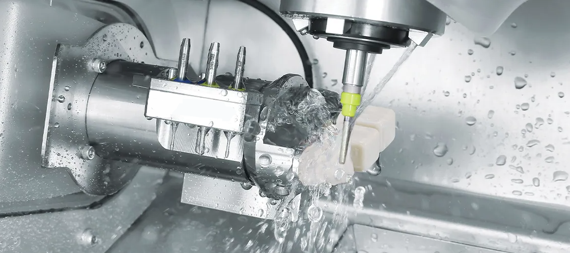
CAM provides a complete manufacturing solution for machines that have a CNC. The design that comes from CAD is imported into the CAM. Then CAM processes it in a way that the CAD can be read and understood by CNC machines. CAM took manufacturing to such a high level of automation that manpower is needed only for data import, feeding of raw material and ejecting the product. All other steps have become automated with the help of CAM.
How CAD and CAM Work Together
CAD and CAM work in conjunction to achieve automation in manufacturing. The design of CAD is processed by CAM which is then fed into CNC machines for further processing.
Impact on Workflow Efficiency
CAD and CAM boost up workflow efficiency by minimizing wastage, reducing time of production, minimizing human errors and bringing up a good consistency of quality. Precion in high end manufacturing also improves.
Difference Between CAD and CAM with Examples
As an example a 3D model is generated in SolidWorks CAD software. It is saved in .STEP file format for instance. This file is fed in to a CAM software for example Master CAM where it is processed. G Code and M Codes instructions are made for the CNC.
The Evolution of CAD and CAM in Modern Manufacturing
The advancement in automation with the help of CAD and CAM has been immense. It allows to perform high precision manufacturing jobs that were previously unimaginable. For instance, the technological advancements in spacecrafts owe some credit to CAD and CAM. Without it, it would be very tedious to manufacture components with such a high precision.

From Manual Drafting to Digital Design
The journey has been long. It was used be a room full of designers who used to take plenty of manhours and sheets of paper to finalize a small design. Now it can be performed on single computer with a single CAD designer.
The Role of CAD/CAM in Industry 4.0
Its impact is huge. It has transformed the manufacturing industry through digital integration and smart technologies.
The Rise of Automation and AI Integration
With the current developments in AI, CAD models can be easily generated. It helps a lot in the conceptualization of designs. The dimensions and geometry od the targeted product can be assessed. As AI is developing further, it might generate CAD models on its own soon. An integration of with AI with CAD and CAM will further minimize the need of manpower, But a lot work has be done towards its improvement.
CAD and CAM in Manufacturing: Applications and Uses
Almost all hi-tech industries use CAD and CAM in their mass production. It allows them to optimize their designs and processes. It brings about a great deal of easiness in maintaining consistency in quality. Thus, compliance with international manufacturing standards becomes easy.
CAD vs CAM vs CAE: Understanding the Difference

CAD, CAM and CAE are distinct but interrelated. A lot has already been discussed about CAD and CAM. Now let's explore CAE.
What is CAE?
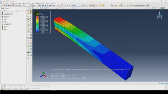
CAE stands for Computer Aided Engineering. It allows its users to simulate different conditions on the 3D models in order to ensure their durability when they are put under actual service conditions. Mainly, it has Finite Element Analysis (FEA) to simulate dynamic or physical problems and CFD (Computational Fluid Dynamics) to check the behavior of fluids.
CAD vs. CAE vs. CAM: How They Complement Each Other
All of these computer aided programs collectively assist in designing, manufacturing and simulations. For instance, a 3D model created in CAD can be simulated in the CAE and then manufactured using CAM.
Benefits of Using All Three in the Design and Manufacturing Process
As discussed above a combination of all three programs make the manufacturing process optimized.
CAD to CAM to CNC
Although CNC machines are capable of creating complex parts automatically with minimum human interaction, but they are unable to understand our ideas and requirements about the designs. So, there must be a language that they can understand. That is G-Codes. Our ideas are conceptualized in CAD and then send to CAM to be processed in G-Codes which allows the CNC to function as per our requirements.
CNC Parts
Almost all types of components can be manufactured using CNC. But the most favorable are those that are intended to be manufactured again and again. For example, the CAD and CAM for Printed Circuit Boards (PBCs) are made once and then millions of PCB are printed on the same pattern.
CAD CAM Software for Plasma Cutting
Plasma cutting can be performed on flat sheets, like steel sheets. The plasma gun follows the path as set by the CAM.
Integration with 3D Printing
With the help of CAD and CAM, actual 3D parts can be manufactured bit by bit and layer by layer. The 3D printer just follow the CAM instructions given by us.
FAQs on CAD and CAM
What is the relationship between CAD and CAM?
Both are computer assisted. CAD is the design and CAM sets its realization.
Can CAD and CAM software be used without the other?
Yes, they can be used independently from each other.
 Tel/WeChat:
  Email:
 Home
Home
 Climb Milling vs Conventional Which is Best


