What is GD&T? Purpose and Rules
 Sep 06,2024

Geometric Dimensioning and Tolerancing (GD&T) is a vital aspect of engineering design and manufacturing, offering methodical approach to defining and communicating admissible limits of variation in a part's geometry. The purpose of GD&T is to ensure that corridor fit together and serve rightly in an assembly, indeed when there are minor variations in their manufacturing process. This companion provides an in- depth disquisition of GD&T, covering its principles, symbols, operations, and significance in ultramodern engineering practices.
What is GD&T?
Dimensions
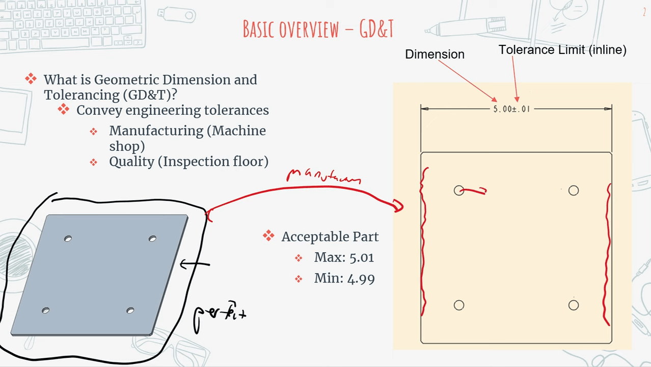
At the core of GD&T lies the conception of confines, defining a part's birth. Dimensions specify the size, shape, and position of features on a part. Expressed in units like millimeters or inches, they are crucial for establishing the nominal figure, the ideal or theoretical confines of a part. Traditional dimensioning provides confines straightforwardly, with little or no indication of how variations might affect the part's function. However, GD&T integrates these confines with geometric tolerances, offering a more comprehensive understanding of how a part should be manufactured and audited.
Units of Measure
Units of measure in GD&T plays critical part in icing delicacy and thickness of the confines and Tolerances specified on engineering drawings. It's essential that all confines and Tolerances are easily defined using a harmonious unit system, whether in millimeters or Homeric( elevation). Use of harmonious units of measure helps help crimes that could arise from unit transformations or misconstructions, icing that corridor manufactured to correct scale and meet the design intent. In global manufacturing terrain, where corridor may be designed in one country and produced in another, significance of formalized units of measure can not be overstated.
GD & T facilitates this by furnishing a universal language that transcends indigenous differences in dimension systems, allowing for flawless collaboration and communication between contrivers, masterminds, and manufacturers worldwide.
This YouTube video covers different geometric characteristics and other key aspects of GD&T including datums, material modifiers (MMC, LMC, RFS), the Envelope Principle, and Independency Principle.
Tolerances
Main part of GD&T is tolerance, defining the permissible variations in a part's geometry. These variations are ineluctable in any manufacturing process, as it's insolvable to produce corridor that are impeccably identical to nominal confines every time. Tolerances specify the range within which these variations are respectable, icing that the part will still serve as intended, it deviates slightly from the ideal geometry. In GD&T, Tolerances are frequently expressed in terms of plus disadvantage values relative to the nominal dimensions. For illustration, a dimension might be specified as 50. 00 mm ± 0. 05 mm, meaning that accurate size of the point can range from 49. 95 mm to 50. 05 mm.
This range represents the Tolerances zone, within which point must fall to be considered acceptable. GD & T also introduces conception of geometric Tolerances, which control specific aspects of a part's figure, similar as its flatness, straightness, roundness, and angularity. These geometric Tolerances are represented by symbols that are placed on engineering delineations alongside the confines, furnishing a clear and terse way to communicate the permissible variations in part's figure.
Datums and Datum References
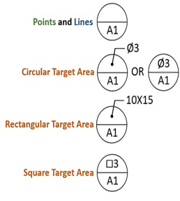
Datums and datum references are essential aspects of GD&T and they serve as reference in the form of point or line or surface used for measurement. A datum is an exact plane, axis, or point which is used for reference to the geometric features of the part. Datum references aid in establishing the position, the attitude and position of the features on a part. These are the reference points through which measurements and inspections of a part are taken and will ensure the part is of the right shape. Because the common datum is achieved through a single point, GD&T guarantees that parts are manufactured and tested alike regardless the process used.
This is particularly true where numeration of components is vital and in the reassembly of different elements that require to intermesh in a coherent pattern. Therefore, using the same datums helps the engineers because it will guarantee that when assembled the different parts will fit well even if they are slightly different in shape.

Figure 1: Datum Symbols and Their Meanings.
Geometric Characteristics
Geometric characteristics in GD&T describe the specific attributes of a part's figure that are controlled by the tolerances. These characteristics include features similar as flatness, straightness, circularity, cylindricity, and more. Each geometric specific is represented by a unique symbol, which is used to specify the permissible variations in that particular aspect of the part's geometry. For illustration, the flatness symbol indicates that a face must be within a specified Tolerances zone, where all points on the face taradiddle within two resemblant planes. Similarly, the straightness symbol controls the permissible divagation of a line or edge from a impeccably straight line, icing that the point remains within a specified Tolerances zone.
These geometric characteristics are critical for icing the functionality of a part, particularly in operations where precise figure is needed for the part to perform its intended function. By specifying geometric Tolerances, masterminds can ensure that the part will meet its performance conditions, indeed if there are slight variations in its figure.
Modifiers
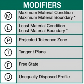
Modifiers in GD&T are used to upgrade the meaning of the symbols and Tolerances, furnishing fresh environment to the specified requirements. Common modifiers include Maximum Material Condition( MMC), Least Material Condition( LMC), and Anyhow of point Size( RFS).
Maximum Material Condition( MMC)MMC indicates the condition of a point where it contains the maximum quantum of material within the specified tolerance. For illustration, a hole at its lowest permissible periphery or a shaft at its largest permissible periphery represents the MMC condition. MMC is frequently used in confluence with positional Tolerances to allow for lesser inflexibility in manufacturing while still icing that corridor will assemble rightly.
Least Material Condition( LMC)LMC represents the condition of a point where it contains the least quantum of material within the specified tolerance. For case, a hole at its largest permissible periphery or a shaft at its lowest permissible periphery corresponds to the LMC condition. LMC is used when the least material condition is critical to the function of the part, similar as in cases where strength or severity is a concern.
Anyhow of point Size( RFS)RFS indicates that the Tolerances applies anyhow of the factual size of the feature. This means that the specified Tolerances must be met irrespective of whether the point is at its MMC, LMC, or any intermediate size. RFS is the dereliction condition for utmost geometric Tolerances unless else specified.

Figure 2: Modifier Symbols and Their Meanings.
For those masterminds who have relatively low power over the production process, modifiers allow setting Tolerances suitable for performance and operation of a specific part. Modifiers can be used to help masterminds balance the need to have functional parts, manufacturability and cost efficiency on the product.
GD&T Inspection and Verification
Acceptance criteria are important for determining whether or not parts meet GD&T specifications, but inspection and verification are indispensable conditions for the total quality management system. Such processes include gauging which is used to determine the size of the part to ascertain whether it lies within certain tolerance regions or checking which examines the shape of the part to find out whether or not it fits within certain tolerance zones. Spot inspection and verification are critical in ascertaining that parts are built, look like, and perform in the way they have been intended to.
tools and techniques employed in GD&T inspection include; CMM’s optical comparators, Laser scanners and of course simple instruments such as calipers and Micrometers. They are particularly important when it comes to GD&T inspection because they supply extremely accurate measurements of complicated geometries. These machines use a probe to touch the part’s surface and record points, which are to be compared with designs on the engineering drawing or the CAD model.
Software tools are also used in inspection of GD&T where computerized methods of comparing results obtained with the set tolerances are employed. Some GD&T inspection software is capable of acquiring data fed from CMMs or other similar devices and then provides report that outlines any discrepancies. They enhance accuracy and reliability of top-end inspections, and at the same time minimize the amount of time and energy that goes into confirming whether specific parts are compliant or not.
In industries where manufacturing precision and reliability are inevitable such as the automobile industry or the manufacturing of medical equipment, inspection and verification are very essential in ensuring that quality and consistency is observed in the production of the commodities. Thus, proper implementation of GD&T standards when it comes to parts means less defects and more durability, less rework and less product failures, and, in general, better and more reliable products.
Purpose and Rules
Purpose of GD&T
Thus, GD&T is mainly aimed at guaranteeing that a part performs its designated task and to interchange it with other parts without creating problems during assembly or later use. By making direction of acceptable variations of shape with respect to a datum, GD&T reduces confusion and ensures that everyone involved in the production of the product is on the same level of understanding. This minimises the potential of making mistakes that would have lead to expenses such as rework, scrap or failure in delivering the final product.
However, application of GD&T is most important where components need to accurately locate with one another, for example in assembled detail. Thus, GD&T means that by keeping each component’s form control relative to some datums, the shape of one part will effect a correct fit and function with another, even though within its class the components may vary slightly in shape. This control is very important for the robustness and quality of the systems used in aviation, automobile, and in the health care field.
Contrastingly, while maintaining functionality and compatibility, GD&T assist in achieving balance between the part performance, ease of production and its cost. It becomes possible to set tolerances suitable for the desired usage of the part; there is no necessary to over design and over price the manufacturing project or under design and over price the manufacturing project.

Fundamental Rules of GD&T
The method of application of GD&T is based on a basic set of rules, often termed as abecedarian rules that form the basis for understanding and applying geometric tolerance. These rules ensure standardization in how thickness, confines and Tolerances are employed and interpreted so as to provide a framework that will be followed by all the interpreters. The following are some of the major rules that are implemented;
Rule# 1 The Envelope Principle( Perfect Form at MMC)
This rule, also known as the" Perfect Form at Maximum Material Condition" rule, states that the geometric form of a point must be perfect when the point is at its Maximum Material Condition( MMC). For case, if a hole is specified at its lowest permissible periphery( MMC), it must be impeccably round, without any divagation from the specified form. This rule ensures that corridor meet strict form conditions when they're at their most critical condition.
Rule# 2 Independency Principle
The Independency Principle allows each geometric Tolerances to be considered singly of other Tolerances unless they're explicitly tied together through modifiers or specific notes on the drawing. This principle ensures that each geometric specific is controlled collectively, which can be critical for features that have different functional conditions.
Rule# 3 Anyhow of point Size( RFS) dereliction Condition
By dereliction, all geometric Tolerances apply anyhow of the factual size of the point unless specified otherwise. This rule provides a birth understanding that the Tolerances zone must be met no matter what size the point is, furnishing inflexibility in the manufacturing process while icing that corridor still serve as intended.
Rule# 4 Limits of Size
This rule states that the size limits specified on a delineation( the outside and minimal permissible sizes) control both the size and the form of the feature. The point must fall within these size limits while also maintaining its geometric form, icing that the part will fit and serve rightly in its assembly.
Rule# 5 Datum Reference Frame Establishment
The detail reference frame is a crucial conception in GD&T, furnishing a match system from which the geometric characteristics of the part are measured. This rule emphasizes that datums must be established from stable, unremarkable features on the part, icing thickness in dimension and examination.
These fundamental rules support the entire GD&T system, providing an organized and systematic method in defining as well as interpreting geometric tolerances. These rules are important to know and use if one works with GD&T because they underpin icing that corridor meet their design intent and function rightly in their final operation.
Documents and Standards
GD&T conforms to colorful transnational norms which insure thickness and delicacross diversified industries and regions. Reported norms which can be supported by solid evidence include:
ISO 2768Defines general Tolerances for direct and angular confines without individual tolerances suggestions. It’s divided into different corridors and grades (e.g., ISO 2768- f for fine tolerances and ISO 2768- m for medium tolerances).
ASME Y 14.5Provides comprehensive guidelines for the operation of GD&T in engineering delineations and models.
ISO 286Establishes tolerances grades for fit classes, generally used in machining and manufacturing.
These norms also cover data exchange and integration, icing that GD&T information can be constantly interpreted across different platforms and software tools.
Limitations of Traditional Tolerancing
Traditional tolerancing styles frequently lead to nebulosity, misconstructions, and functional limitations in part design and manufacturing. These styles may not adequately define the connections between features or account for how variations in one point affect others. GD&T addresses these issues by furnishing a clear and unequivocal language for describing part figure. This clarity improves communication between contrivers and manufacturers, reduces the threat of crimes, and enhances the overall quality of the final product.
Chinese Machining Services
Precision Engineering for Innovators
Send drawings to info@tuofa-cncmachining.com
Faster and Cheaper
How Tuofa Utilizes GD&T to Deliver High-Quality, Cost-Effective Custom Parts
Tuofa China leverages the GD&T system to deliver high-quality, custom-made parts that meet precise design specifications. By using GD&T, Tuofa enhances manufacturing efficiency, helps customers control production costs, and ensures the interchangeability and assembly reliability of the parts. This approach not only improves the overall quality of the parts but also streamlines the production process, providing customers with efficient and cost-effective solutions.
 Tel/WeChat:
  Email:
 Home
Home

 Toughness vs. Resilience Material: Comprehensive Guide


