Understanding CNC Drawings and Related Concepts
 Jul 31,2024

Computer Numerical Control (CNC) technology is revolutionizing manufacturing. It enables precision and efficiency in the production of complex parts. CNC machines, controlled by computer programs, are used to shape and finish materials with exacting accuracy. This guide covers essential topics related to CNC drawings. It also covers their importance in the manufacturing process. Finally, it covers how various software tools are used to create and interpret these drawings.
What is a CNC Drawing?
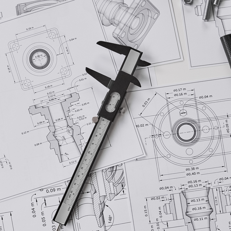
CNC drawings are detailed blueprints that communicate specific instructions and specifications to machinists. These drawings are critical for ensuring that the final product meets design requirements and quality standards. They include dimensions, materials, tolerances, and other technical information. This information is needed to guide the machining process.Keep your drawings safe.By providing a clear visual representation of the part to be manufactured, CNC drawings help prevent errors. They also ensure consistency in production.

What Does CNC Stand For?
CNC stands for Computer Numerical Control. This technology allows for the automation of machine tools through the use of computer-generated commands. CNC systems are used in a variety of applications. These applications include milling, turning, and drilling. They create parts with high precision and repeatability. The automation provided by CNC technology increases efficiency. It reduces human error. It also enables the production of complex geometries that would be difficult or impossible to achieve manually.
Is FreeCAD Good for a CNC Machine?
FreeCAD is an open-source CAD software. It offers a range of features suitable for designing parts for CNC machining. It provides tools for creating detailed 3D models. These models can then be converted into CNC programs. Compared to commercial CAD software like SolidWorks or AutoCAD, FreeCAD offers fewer advanced features. However, it is a viable option for users with budget constraints or specific open-source needs.
|
Pros |
Cons |
|
Free to use |
Challenging learning curve |
|
Supports various file formats |
Less robust than commercial software |
|
Customizable with plugins |
|
|
Strong community support |
|
Differences Between CNC and CAD
CAD is used to create detailed digital models of parts and assemblies. CAD software allows engineers and designers to visualize and refine their designs before manufacturing. CNC uses CAD models to generate machine instructions. CNC software translates these models into commands. These commands control the movement and operation of machine tools.
Functionality
CAD focuses on design and modeling, while CNC focuses on machining and production.
Workflow
CAD is the initial step in the design process, creating a blueprint for the part. CNC follows by using this blueprint to manufacture the part.

Technical Drawings for CNC Machining
Technical drawings are essential for translating design concepts into manufactured products. Key components of CNC technical drawings include:
Title Block
Contains essential details. These details include the part name, designer, date, scale, and other relevant information.
Orthographic Views
Provides multiple perspectives. These perspectives include the top, front, and side. They fully describe the part's geometry and dimensions.
Isometric View
Shows a 3D representation of the part. This allows better visualization of its overall shape and structure.
Section Views
Reveals internal features by cutting through the part. It shows hidden details that are not visible externally.
Detail Views
Highlights specific areas of the part that require close attention. It provides detailed representations for critical features.
Notes to the Manufacturer
Include important instructions and specifications. These instructions and specifications are not covered in the drawings. These elements ensure that machinists understand all aspects of the part. This ranges from overall dimensions to intricate details.
Arduino CNC Drawing Machine
Arduino CNC drawing machines are DIY projects. They use Arduino microcontrollers to control drawing tools. These machines can create drawings or engravings on various materials.
Basic Components
Arduino CNC drawing machines are built using several key components. These components work together to control the drawing tool precisely.
Arduino Board
Acts as the brain of the machine. It processes inputs and controls the outputs to guide the drawing tool.
Stepper Motors
Control the movement of the drawing tool with high precision. They enable accurate and detailed drawings.
Frame
Provides a stable structure that holds all the components together. This ensures smooth and accurate operation.
Applications and Project Ideas
Arduino CNC drawing machines can be used for various creative and technical applications. This makes them versatile tools for both hobbyists and professionals.
Engraving
Create detailed engravings on materials like wood, metal, or plastic. These are suitable for custom art or professional work.
Drawing
Produce precise technical drawings or artistic designs. This allows for accurate replication of complex patterns and images.
Multi-Axis CNC Machinery
Multi-axis CNC machines can move the cutting tool or the part along multiple axes simultaneously. Common configurations include 3-axis, 4-axis, and 5-axis machines. These allow for more complex and precise machining operations.
Benefits of Multi-Axis Machining
Multi-axis machining offers several advantages over traditional methods, including:
Complex Part Geometry
Capable of producing intricate shapes and features. These would be difficult or impossible with fewer axes.
Reduced Setup Time
Multiple operations can be performed in a single setup. This reduces the need for multiple fixtures and repositioning.
Improved Surface Finish
Better control over tool paths and angles leads to smoother finishes. This results in higher quality parts.
Examples of Multi-Axis CNC Machinery
There are various types of multi-axis CNC machines, each suited to specific applications:
5-Axis Milling Machine
Ideal for manufacturing aerospace components and medical implants. It offers the ability to machine complex parts with precision.
4-Axis Lathe
Used for producing complex rotational parts. These are found in automotive and industrial applications.

What Is a Technical CNC Machining Drawing?
Technical CNC machining drawings provide detailed instructions for manufacturing parts. They differ from standard technical drawings. They include specific information relevant to CNC machining. This information includes tool paths, machine settings, and process sequences.
Dimensions and Tolerances
Dimensions and tolerances define the exact size and allowable variations in the part's geometry. These specifications ensure that each manufactured part meets precise standards. They ensure the part fits together with other components as intended.
Material Specifications
Material specifications indicate the type of material to be used for manufacturing the part. This includes details on the grade, properties, and any specific treatments required. This ensures the part meets the necessary performance criteria.
Surface Finish
The surface finish specifies the desired texture and smoothness of the part's surface. This is critical for both the functionality and aesthetics of the part. It influences factors such as friction, wear, and appearance.
How to Convert AutoCAD Drawing to CNC Program
Converting an AutoCAD drawing to a CNC program involves several steps. These steps ensure compatibility and precision in the final product.
Create the Drawing
Design the part in AutoCAD with all necessary details. Ensure that dimensions, tolerances, and material specifications are accurately represented.
Export to DXF/DWG
Save the drawing in a CNC-compatible format like DXF or DWG. These formats are widely supported by various CAM software and CNC machines.
Import to CAM Software
Use CAM software such as Fusion 360 or Mastercam to import the drawing. This step involves translating the 2D/3D design into a format that can be used for toolpath generation.
Generate Toolpaths
Define the machining operations and toolpaths required for the part. This includes selecting the appropriate tools, speeds, and feeds to ensure optimal machining performance.
Post-Process
Convert the defined toolpaths into machine code (G-code) for the CNC machine. This step is crucial for ensuring that the CNC machine accurately executes the machining operations.
Preparing a Technical Drawing for CNC Machining
Ensure dimensions, tolerances, materials, and detailed views are accurate for precise CNC machining.https://www.tuofa-cncmachining.com/
Define Views and Dimensions
Create orthographic and isometric views to provide a comprehensive representation of the part. These views help ensure that all dimensions and features are accurately captured.
Add Construction Lines
Guide the placement of features and dimensions by adding construction lines. These lines help maintain consistency and accuracy throughout the drawing process.
Specify Threads and Holes
Indicate the size and type of threads and holes required for the part. This includes detailed specifications to ensure proper fit and function in the final assembly.
Apply Tolerances
Define acceptable variations for critical dimensions. This ensures that the part meets performance and quality standards. This is essential for parts that require precise fits.
Complete the Title Block and Notes
Include all necessary information for the machinist in the title block and accompanying notes. This ensures clear communication of all relevant details. These details include the part name, material, and special instructions.
Importance of Validation and Review
Ensures accuracy, prevents errors, and maintains quality in CNC machining and final product.
Check for Completeness
Ensure all necessary details are included in the drawing. This includes verifying that all views, dimensions, and specifications are present and clearly defined.
Review for Accuracy
Verify the accuracy of dimensions, tolerances, and notes to prevent errors during machining. Double-checking these elements is crucial for ensuring the part is manufactured correctly.
Validate with Stakeholders
Get feedback from engineers, machinists, and other relevant parties. This confirms that the drawing meets all requirements. This collaborative review process helps identify and resolve any potential issues before production.
conclusion
Understanding CNC drawings and related concepts is crucial for efficient and precise manufacturing. CNC drawings provide detailed blueprints. These blueprints guide the machining process. They ensure design specifications and quality standards are met. Tuofa factory in china by leveraging software tools like FreeCAD and AutoCAD, manufacturers can create, convert, and interpret these drawings. This allows them to produce complex parts. With advancements in multi-axis CNC machinery, the capability to produce intricate geometries has significantly improved. This further enhances the efficiency and accuracy of the manufacturing process.
 Tel/WeChat:
  Email:
 Home
Home
 Mastering Thread Milling: Techniques and Best Practices


