Tel/WeChat:
  Email:
 Home
HomeTypes of Gears: Designs, Applications & Robotics Integration

 Apr 03,2025
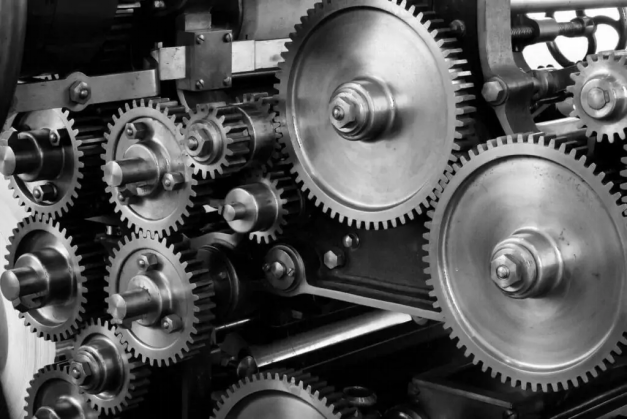
Since the Industrial Revolution, advanced machines have been manufactured. The gears are the backbone of these machines. They are a source of power transmission in these machines. From a watch to an aircraft or a space shuttle, gears perform an important role in performing accurately. The research shows that 90% of the total machines use gears for proper functioning. This article presents a comprehensive guide to these gears, their types, and their applications and discusses how they revolutionised robotics integration. Let's define what the gears are and how they fundamentally power transmission.
What Are Gears? The Fundamentals of Power Transmission
Gears are the tooth wheels that transfer motion and force between shafts. They are fundamental in power transmission because they control speed, torque and direction. Their role has made them a vital component from a bicycle to a spacecraft.
Gear Terminology Explained:
The following are the main terminologies in a gear:
- Pitch
Pitch means the distance between two teeth
- Module
Metric measure of tooth size
- Pressure Angle
It is the angle between the tooth face and the gear tangent. It typically remains an average of 20° or 14.5°
How Gears Work?
In this section, we will see how a gear works. Gears transmit power to the shafts while enabling the following key features.
Torque Multiplication
Torque multiplication means when two gears, the smaller one drives the larger one, the output torque increases.
- Formula
Output Torque = Input Torque × (Teeth on Driven Gear / Teeth on Driving Gear)
Speed Reduction
In torque multiplication, as the output torque increases, overall speed is reduced.
- Formula
Output Speed = Input Speed × (Teeth on Driving Gear / Teeth on Driven Gear)
Gear Teeth Geometry Explained
The geometry of a gear is the base of how a gear will perform and means smooth transmission of power. The common profiles are involute and cycloidal. Let's understand them:
Involute Teeth
It comes with a curved shape that is generated from unwrapping a string from a base circle.
- Why do 90% of gears use involute teeth?
There are five reasons why 90% of gears are of involute geometry.
- Constant Velocity Rations
- Easier manufacturing
- Wear Resistance
- Zero Backlash
- Tolerance
Cycloidal Teeth
Shape: Peaked and generated from rolling circles along a pitch circle.
They are considered best for High-impact loads.
Key Components:
Now, we will briefly discuss some key components of Gear
Hub
Central Mounting Point
Rim
Outer tooth-bearing ring
Shaft Connections
Transmit power to the other components
Teeth
Determines meshing efficiency
Types of Gears by Axial Direction
Let's discover some types of gears by axial direction:
Parallel Axis Gears
- In these gears, shafts move parallel to each other
- Key types include Spur Gears, Helical Gears, Double Helical Gears
- Parallel-axis gears provide high efficiency and are best for constant-speed applications
- Applications are gear boxes, machinery

Intersecting Axis Gears
- Shafts meet an angle, often it is 90 degrees
- Key types of this type of gear are Straight Bevel Gears, Spiral Bevel Gears, Hypoid Gears
- These gears can change power direction efficiently
- Can reduce noise in automotive applications
Non-Parallel/Non-Intersecting Gears
- In these gears, neither shaft intersect nor move in parallel direction
- Key types are worm gears and crossed helical gears
- Best for extreme speed reductions
- Compact design for tight spaces
- The most common example is the elevator
The 7 Core Types of Gears & Their Mechanics
In this section, we are going to discuss 7 types of gears and their mechanics:
Spur Gears: Simplicity & High Efficiency
- Shape & Structure
Straight teeth parallel to the shaft
Cylindrical shape with external or internal teel
- Working principle
Teeth fully engaged at once, transferring the power without axial thrust
- Performance & Applications
Provides 90-95% efficiency in power transmission
Applications are conveyors, gear pumps
External vs. Internal Spur Gears
Here is the brief difference between the external and internal spur gears given in the following table:
|
External Spur Gears |
Internal Spur Gears |
|
Teeth in external space |
Teeth on inner surface |
|
Used in Gear trains |
Used in planetary gears |
Helical Gears: Quiet Operation & High Load Capacity
- Shape & Structure
Structure is angled teeth, but shape is cylindrical but longer than spurs
- Working Principle
Teeth engage slowly and generate axial thrust
- Performance and Applications
Handles higher loads
Reduced noise, best for automotive transmissions
Single vs. Double Helical (Herringbone) Designs
|
Single Helical |
Herringbone |
|
Needs thrust bearings |
Two mirrored helices cancel axial thrust |
|
Common in pumps |
Common in turbines |
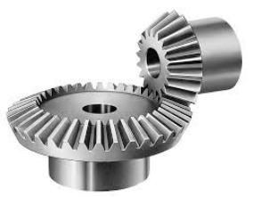
Bevel Gears: Angular Power Transmission
- Shape & Structure
Its shape is conical, with teeth cut at an angle and shafts intersect
- Working Principle
Transmits power between non-parallel shafts
- Performance and Applications
Higher torque, smooth operation, reduced noise
used in load-bearing, aerospace applications
Straight vs. Spiral vs. Hypoid Bevel Gears
|
Type |
Teeth Design |
Advantage |
Application |
|
Straight |
Straight, tapered |
Simple, low-cost |
Differential drives |
|
Spiral |
Curved, angled |
Smother, quieter |
Helicopter transmissions |
|
Hypoid |
Offset, spiral |
Compact, high torque |
Automotive rear axles |
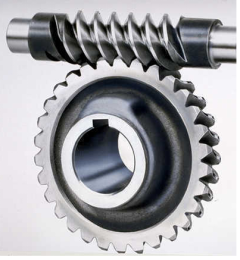
Worm Gears: Compact Ratios & Self-Locking
- Shape & Structure
Shafts are non-parallel
Shape: Worm(screw) + worm wheel(gear)
- Working Principle
Worm's threads slide against wheel teeth
- Performance and Applications
Self-Locking
Used in conveyor brakes
Rack & Pinion: Converting Rotary to Linear Motion
- Shape & Structure
Pinion (round gear) + Rack (flat, toothed bar)
- Working Principle
The pinion rotates, which moves the rack linearly
- Performance and Applications
Provides precise linear motion and is used in CNC machines, steering systems
Planetary Gears: Precision & Torque Density
- Shape & Structure
Sun gear (centre) + Planet gear (rotating) + Ring gear (outer)
- Working Principle
There are multiple contact points which distribute the load evenly
- Performance and Applications
Provides high torque in small spaces and is used in robotics, wind turbines
Spline Gears: Multi-Key Shaft Connections
- Shape & Structure
Longitudinal teeth on shafts/hubs
- Working Principle
Multiple teeth evenly distribute torque
- Performance and Applications
Provide Sliding connections and are used in tractors and aircraft
Advanced Gear Types for Specialized Applications
Specialized applications include aerospace and robotics. The structure of these applications is complex and uses very carefully designed advanced gears. Let's study some advanced types of gears in this section.
Harmonic Drive Gears (Robotics & Aerospace)
These gears are also known as Strain waving gearing. They use a flexible spline deformed by an elliptical wave generator to mesh with a rigid circular spline.
The properties of these gears are:
- Zero backlash=> critical for robotic arms
- Compact & Lightweight
- High precision used in surgical robots
Applications
Industrial Robots such as Fanuc, Kuka arms
Satellite solar array development
Magnetic Gears: Contactless Torque Transfer
Magnetic gears work by using permanent magnets arranged in pole pieces to transfer torque without physical contact. There are multiple tools, i.e. outer rotor, inner rotor and a stationary module, which control magnetic flux.
They are useful because of:
Maintenance-free gears
Silent Operation
Overload Protection
Applications
- Wind Turbines
- Electric Vehicle Transmission
Non-Circular Gears
How They Work:
- Featureoval, triangular, or custom-shapedpitch curves instead of circles
- Convert constant input speed intoprogrammable output motion
Key Properties are:
- Speed Modulation: Output RPM varies per rotation
- Mechanical Programming: Replaced cam systems in packaging machines
The following table is the summary of the above discussion:
|
Type |
Torque Range |
Precision |
Best For |
Cost Factor |
|
Harmonic Drive |
1–500 Nm |
±0.1 arc-min |
Robotics, Aerospace |
4× |
|
Magnetic Gears |
5–200 Nm |
±0.5° |
Medical, EVs |
5× |
|
Non-Circular |
1–200 Nm |
Speed-dependent |
Packaging, Printing |
3× |
Types of Gear Teeth Designs & Their Impact
Types of teeth affect the gear's performance, lifespan, efficiency, etc. In this section, we will discuss types of gear teeth designs and their impact on the performance of these gears.
Tooth Profiles Compared: Spur vs. Helical vs. Curvic
Spur Gear Teeth
- Shape:Straight, Parallel to gear axis
Notable Properties:
- High Efficiency (98-99%)
- Simple and cost-effective manufacturing
It is considered best for low-speed, high-torque applications such as conveyors and manual transmissions.
Helical Gear Teeth
- Shape: Angled, gradually tapered
- Properties include quieter operations and higher load capacity
- Best for industrial pumps, automotive transmissions
Curvic Gear Teeth
- Shape: Curved profile with multiple pressure angles
Properties are:
- Smoother meshing
- Can handle misalignments better
This type of gear teeth is best for aerospace, high-precision gearboxes.
Gear Teeth Grinding vs. Hobbing: Which is Better?
Hobbing is a faster process but leaves micro-burs on the surface, while Grinding can achieve a surface finish of Ra 0.2μm.
|
Method |
Process |
Accuracy |
Best For |
|
Hobbing |
Cuts teeth with a rotating hob |
±0.05 mm |
High-volume spur/helical gears |
|
Grinding |
Abrasive wheels finish pre-cut teeth |
±0.005 mm |
High precision (e.g., aerospace, robotics) |
Backlash Control Strategies
Backlash is an issue which occurs between meshing teeth. It causes positioning errors and vibrations. That's why it is important to tackle this issue. Some strategies to solve this issue are given below:
- Alteration in the Design
- Manufacturing fixes
- Maintenance Adjustments
Best Materials for Different Gear Types
The selection of inappropriate materials for gear types affects mechanical properties and so the performance of that gear. Let's see which materials are considered best for gear types and why in this section.
Steel Alloys: Strength vs. Weight
In this table, you can see different steel alloys which are used for gear types. Steel excels in high-load capacity, i.e. 500+ Nm torque, but it is heavy.
|
Alloy Type |
Hardness (HRC) |
Tensile Strength (MPa) |
Key Advantages |
Common Uses |
|
AISI 4340 |
28–32 |
1,000–1,200 |
Toughness, fatigue resistance |
Automotive transmissions |
|
8620 (Case-Hardened) |
58–62 (surface) |
800–1,000 |
Wear-resistant surface, ductile core |
Aerospace gearboxes |
|
Stainless (17-4PH) |
40–45 |
1,100–1,300 |
Corrosion resistance |
Marine, food processing |
Plastics & Composites: Quiet, Lightweight Solutions
Plastics and composites are lightweight and used in noise-sensitive applications.
|
Material |
Tensile Strength (MPa) |
Max Temp (°C) |
Key Advantages |
Common Uses |
|
Nylon 66 |
80–90 |
120 |
Self-lubricating, dampens noise |
Conveyor systems, printers |
|
Polycarbonate |
55–75 |
135 |
Impact-resistant, transparent |
Food-safe machinery |
Emerging Materials: Carbon Fiber & 3D-Printed Gears
Carbon fiber & 3D-printed gears are emerging materials in the field of gears. They are specialized materials and are used for prototyping and extreme conditions.
|
Material |
Strength-to-Weight Ratio |
Unique Benefits |
Current Limitations |
|
Carbon Fiber-Reinforced |
5× higher than steel |
Near-zero thermal expansion, vibration damping |
Brittle under impact |
|
3D-Printed Titanium |
Comparable to 4340 steel |
Complex geometries (e.g., topology-optimized teeth) |
High cost (~$500/kg) |
Gears in Robotics: Precision Requirements & Trends
Robotics is an emerging technology in which robots are manufactured. These robots require extreme precision and reliability from the gears. That is how a gear meets the requirements of a robot.
Cobots vs. Industrial Robots: Gear Specifications
In the following table, we have used the example of two types of robots and then mentioned the requirements for the gear:
|
Specification |
Cobots (Collaborative Robots) |
Industrial Robots (e.g., SCARA, 6-Axis) |
|
Torque |
5–50 Nm (safety-limited) |
50–500 Nm (high-power motors) |
|
Backlash |
<0.01 mm (for human-safe precision) |
<0.05 mm (balance of speed/accuracy) |
|
Size |
Compact (ø20–50 mm gears) |
Larger (ø50–200 mm gears) |
|
Key Gears Used |
Harmonic drives, planetary gears |
Precision helical, cycloidal drives |
Miniature Gears for Surgical & Micro-Bots
The teeth of these gears are very small, i.e. smaller than human hair, which is 0.1–0.5 mm module gears.
To meet such requirements, the following materials are potentially used:
- Stainless Steel
- PEEK
- Ceramics
Anti-Backlash Designs for Positioning Accuracy
First, we need to know what backlash is. It is a play between meshing teeth, which causes positional errors. For anti-backlash designs, these are the changes in the design:
- Preloaded dual gears
- Flexible Splines
- Torsionally Stiff Materials
Gear Design Considerations for Engineers
To get high efficiency from the gears, engineers must understand the following design-related concepts:
How To Calculate Gear Load Capacity (AGMA Standards)?
- First, determine basic things
Module
Number of teeth
Face width
- Calculate the bending stress
- Calculate the contact stress
- Compare to AGMA available stresses
How to Select Lubrication for High-Load Gears?
Lubrication for high-load gears is selected based on the applications. For instance, EP Gear Oil for High-Torque industrial applications.
How to Reduce Gear Noise in Precision Systems?
These are some advanced techniques that reduce noise in precision systems:
- Tooth profile optimization
- Material Damping
- Microgeometry Corrections
Why Are Custom Gears So Expensive and Hard to Find?
The custom gears are expensive and hard to find because of their manufacturing complexities. Their designs are complex, and the respective advanced machines are required to manufacture them.
Why Do "Standard" Gears Don't Fit Modern Needs?
There are many reasons such as:
- Lightweight is the primary requirement in the transport industry. Standard gears are not lightweight, so they can't fit.
- Standard gears do not use advanced materials
- The geometry of these gears is not useable in modern machines
Why Small-Batch Gears Cost More?
Because of low-volume production, small-batch gears cost more. For instance, see the following table:
|
Factor |
Small Batch (50 units) |
Mass Production (10,000+ units) |
|
Setup Time |
8–12 hours (CNC programming, fixturing) |
Amortized to minutes per unit |
|
Tooling Costs |
500–500–2,000 (custom hobs/grinding wheels) |
$0.10/unit |
|
Material Waste |
30–50% (trial runs) |
<5% (optimized processes) |
|
Unit Cost |
50–50–500/gear |
1–1–20/gear |
Alternatives: Modular Kits vs. 3D Printing
Modular Gear Kits are pre-made tooth modules which are 50% cheaper than custom gears.
3D printing uses advanced materials such as SLS Nylon for gear manufacturing and can be used for complex geometries as well. Its tooling cost is 0/day.
Conclusion
In this article, we discussed gears, their types, teeth designs, etc. We can conclude that the gears are the important components of any machine, from bicycles to aircraft. Gears are specialized tools for power transmission, but they also contribute to the design of robots. Many advanced materials, such as composites and advanced technologies like 3D printing, are used in robotics to manufacture specialized gear.
FAQs
What are the 3 uses of gears?
- Speed Adjustment
- Torque Multiplication
- Motion Direction Change
What is the most common type of gear?
The structure of Spur gears is simple, but they are efficient in working; that's why spur gears are the most common type of gear.
 Laser Etching Compared: Engraving, Marking, CNC Machining