Tel/WeChat:
  Email:
 Home
HomeTool Wear Patterns: Types and Solutions

 Published:Feb 26,2025
In simple terms, tool wear is the material loss during cutting and can negatively affect the geometry and functionality of tool. If it is excessive, it can also affect the results of cutting on workpiece. Tool wear can cause damages, failure or scrapped parts or rework.
What is Tool Wear? Understanding the Basics
Tool wear is a breakdown of tools which occurs gradually over time during material removal process. The sharpness and functionality of tools affect severely and results in tool failure. Thermal and mechanical stress can cause tool wear. In most cases, heat and abrasion are the cause of tool wear.
Definition of Tool Wear and Tool Failure
Tool wear is cutting tool failure which is caused by friction, heat and stresses in material removal process. Cutting tool failure is when a tool cannot be used any longer. Excessive wear causes plastic deformation and leads to cutting tool failure.
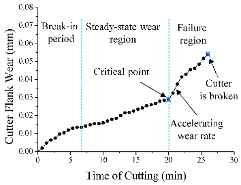
The Three Stages of Tool Wear
Tool wear occurs in three stages.
- Initial Wear Stage:
At this initial stage, a smooth surface on tool edges and a normal wear rate.
- Steady Wear Stage:
The wear stabilized at a constant level and tool performs efficiently with minima degradation in functionality.
- Failure stage
As the tool wear continues, the edges erodes and lead to rapid increases in wear rate. This causes workpiece with poor finish, less machining accuracy, machining tool degradation and higher vibration cause tool failure in material removal process.
Tool Wear vs. Tool Life: What's the Difference?
Tool wear is a gradual breakdown of cutting tool. It causes cutting tool failure and tools can no longer be served for cutting. Tool life is the time a tool can be used before failure or being replaced. It is normally affected by cutting speed, depth or fluid and tool shape
Types of Tool Wear and Their Mechanisms
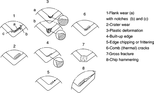
Tool wear can occur in different types.
Flank Wear
This occurs at the edges of cutting tools. Tiny grooves run parallel to the direction of cuts. The cause of flank wear is friction between tool and workpiece. And diffusion of higher temperature by high cutting speed causes flank wear. It causes poor surface finish, inaccurate dimensions, machining tool degradation and reduces cutting tool life
Crater Wear
This occurs when a depression is developed in the cutting tool's rake face. Heat and friction cause the wear and result in flank chip off, thicker chips formation and low surface quality.
Built-Up Edge (BUE)
It is a pileup of material on cutting tools. This occurs on the flank face while machining. It is normally caused by low speed, work-hardened workpieces and chipping off from the cutting tool and sticking to workpiece. This can be eliminated by using lubricants and coolants at optimal cutting speed.
Notch Wear
It is a localized wear on a cutting edge. Abrasion or hard material results in notch wear and can cause tool failure. Heat in higher amount can also cause this wear. It can be avoided by using harder cutting tool and using lubricant and coolants
Chipping and Edge Breakage
It refers to a mechanical failure. A small amount of material breaks off from the cutting edge. Excessive stress or sudden impact can damage the cutting edges while machining. Other factors that can cause chipping and edge breaking are vibrations, hard inclusion or improper cutting speed.
Thermal Cracks
These cracks occur in perpendicular direction to cutting edges. The thermal wear mechanism is a rapid fluctuation in temperature that causes expansion and contraction stresses inside the tool. This can cause chipping, machining tool degradation or premature failure. This normally occurs in milling operations while interrupted cuts. These are identified as visible cracks all over the face of cutting tools.
Plastic Deformation
It is the most common phenomena that occurs in material. material gets plastically deformed after being stressed beyond its elastic limit. In cutting tools, the material gets softened and flows under the thermal wear mechanism. This permanently changes its change without breaking. This reduces the sharpness of edges and reduces tool life and causes machining tool degradation
Key Indicators and Measurement of Tool Wear
Tool Wear Measurement Techniques
Tool wear measurement is quantifying the wear on cutting tools. There are two methods to measure tool wear.
- Direct measurement
It uses visual inspection by using microscope or any vision system to monitor the tool wear directly.
- Indirect measurement
It used sensors to measure related parameters, like vibrations, forces, temperatures that are corelated with tools.
CNC Machine Monitoring: Detecting Wear During Machining
Wear detection in CNC machine is done by analyzing sensor data. These include cutting forces, vibrations, power consumption and acoustic emissions. Any change indication in tools condition is monitored by these parameters before it worn down and allows timely tool replacement and their optimization.
Role of Tool Wear Mechanisms in Measurement Accuracy
Tool wear mechanism significantly affects the measurement accuracy. It gradually changes the geometry of a cutting tool which results in tool degradation, dimensional inaccuracy and improper precision of parts. With the tool wear, the sharpness of cutting edges reduces and causes surface roughness and poor machining accuracy on the machine parts. Thus, affecting the measurement accuracy by reducing it.
Causes of Tool Wear in CNC Machining
Cutting Wear and Machine Tool Edge Stress
High stress and friction generated during the machining process causes cutting wear. This makes the tool lose its material and leads to poor edge sharpness and reduces tool's life. The stress created between tools and workpieces leads to the tool degradation and wear mechanisms such as flank wear and crater wear.
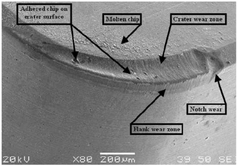
Tungsten Carbide Insert Wear Types: Examples and Analysis
Tungsten carbide insert have crater wear, chipping due to excessive heat. heat from the workpiece affects the tungsten carbide grains which convert in to pit on the rake face. This can lead to chip-off or rapid flank wear. This can be reduced by using coolant and optimal cutting speed
Avoiding Wear on Machine Components
Machine components can be secure from wear by proper lubrication, wear-resistant material, keeping correct alignment, minimize friction and stress on movable items. Timely repairing, vibration analysis, and following proper procedures.
How to Prevent Tool Wear and Optimize Tool Life
Solutions to Prevent Flank Wear in Carbide Turning Inserts
The flank wear in carbide turning inserts can be prevented by using optimize cutting speed and feed rates, high wear resistant carbide material, coolant application, correct insert geometry, and by applying specialized coatings to the insert surface. These all reduce the friction and heat generation by thermal wear mechanism
Coatings and Lubricants to Minimize Cutting Wear
Coatings and lubricants reduce wear by reducing abrasion and heat. Coating protects the underlying material, improve tool hardness, heat resistance, and lubricity. Lubricants improves the machining accuracy, reduces wear and friction
Adjusting Cutting Parameters to Reduce Wear
Cutting parameters optimization is an important aspect to reduce wear. The parameters like lower cutting speed, less feed rate and shallow depth of cut reduce the overall load on tool, put less strain on edges and generate less heat in thermal wear mechanism.
The Role of High-Efficiency Milling in Reducing Wear
High Efficiency Milling is a technique for roughing which used a lower Radial Depth of Cut and a higher Axial Depth of Cut. This reduces the chance of failure and delays tool wear with improving efficiency, material removal rate and improving tool's life.
Importance of Machine Maintenance in Preventing Tool Wear
Machine maintenance is important to prevent tool wear. It ensures optimal procedure, reducing friction, heat generation, and excessive stress on the cutting tools. This extends the tool's life, improves production quality. However, if neglected, this can cause tool degradation, reduces quality and increase costs
Tool Wear Patterns and Their Optimization Strategies
Flank Wear and Carbide Turn Inserts: Problems and Solutions
Flank wear on carbide turn inserts occur due to high cutting speed, low hardness material and improper coolant which causes high heat generation on edges. To solve this, use low cutting speed, high-resistant material, coolant with good flow at cutting zones.
Crater Wear and How to Mitigate It
Crater is a depression forms in rake face. It occurs due to high temperature during cutting. This can be mitigated by reducing cutting speed, coolant application, cutting tools with proper coating and design to manage heat flow.
Handling Built-Up Edges in Tough Materials
Built-up edges can be handled by using relatively high speed to generate more heat that can prevent material from sticking. Use sharp cutting edges, a positive rake angle, efficient chip removal can reduce the material build-up.
Optimizing Chip Formation for Better Tool Life
Tool life can be improved by selecting appropriate cutting feed rate, speed, and rake angle, sharp cutting edges, coolant, and effective chip beakers
Real-Life Examples of Tool Wear
Common Carbide Insert Wear Types
The common types of carbide insert wear are flank wear, crater wear, notch wear, thermal cracks, plastic deformation and build-up edges.
Case Studies on Tungsten Carbide Notch Wear
In this case study, ceramic insert has flank, notch and crater wear. This occurred due to high-speed finish of hardened AISI-D6 using multi-performance characteristics.
Industry-Specific Tool Wear Challenges and Solutions
Common challenges in an industry are fast wear and tear tool or tool degradation due to delicate geometries and small parts. It is solved by regular inspection and replacement of tools, using high wear material and normal cutting speed to improve tool life
How to Extend Tool Life in CNC Machining
Tips to Extend Tool Life
- Use correct tool design
- Optimize the cutting parameters
- Using cutting fluid
- Prevent chip built-up
- Apply tool coating
- Regular inspection and maintenance
Calculating Tool Life for Maximum Efficiency
Taylor's Tool Life Equation can be used to measure efficiency
Vn = C
Where V is the cutting speed, "T" is the tool life, "n" is a constant for tool and C is constant specific to the machining process.
FAQs on Tool Wear and Optimization
What Are the Consequences of Excessive Tool Wear?
Excessive tool wear reduces machining accuracy, longer production cycle, poor surface quality, high tool replacement cost, tool degradation or cutting tool failure and can damage the workpiece.
What Are the Best Ways to Measure Tool Wear?
The best way to measure tool wear is using a microscope to monitor cutting edges.
 CNC Accuracy: How to Achieve Precision in Machining