State-of-the-art skills in machining thin-walled shell-and-tube hardening hardware
 Nov 19,2022

Background Art: At present, Tuofa CNC Machining has received an order from the American automobile industry. During the machining process, the thin-walled shell and tube hardware uses 35CrMnSiA steel pipe materials, which are quenched after rough machining, and the tensile strength is greater than 1100MPa. The clamp device used in the mass production process of the CNC lathe adopts the slotted expansion shoe type open shoe clamp device to clamp the thin-walled tube shell quenching hardware.
In the processing process, to facilitate the loading and unloading of the workpiece on the fixture, there is a certain gap between the inner diameter of the clamping shoe and the outer diameter of the clamped workpiece, and the outer diameter of the expansion shoe and the inner diameter of the clamp. Due to the large clamping force of the hydraulic-pneumatic clamping device, the contact area between the clamping shoe of the fixture and the workpiece is small, and the clamping force does not act on the surface of the workpiece evenly, resulting in deformation, which is the key to the production of thin-walled tube shell hardware products. The size is often in the upper and lower limit sizes or out of tolerance after processing, which also leads to low processing accuracy, unstable quality, and a high rejection rate.
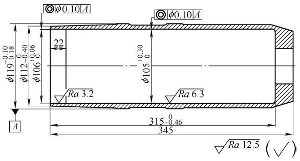
Thin-walled shell-and-tube hardware
Improvement Skills: The purpose of this operation method is to provide a processing method for thin-walled shell and tube hardware, which not only solves the problems of unstable quality and high rejection rate but also solves the clamping deformation that occurs in the processing of thin-walled shell and tube hardware. question.
Technical solution: The processing method of thin-walled shell-and-tube hardware specifically includes the following steps:
Blanking or forming blanks
This part is processed with thick-walled pipe material 35CrMnSiA. If the structure of the part is not suitable for processing with thick-walled pipe material, to avoid material waste, and the parts do not need to withstand high overload, the thin-walled pipe material can be used to close the process, and the outer diameter of the pipe head is partially Forming, inner diameter shrinkage, to meet the blank size requirements; if the part needs to withstand a certain high overload, and its comprehensive mechanical properties have corresponding requirements, the die forging can be considered to form the blank under the premise of saving costs, but it must be based on product design requirements. Corresponding blank production technical requirements.
Rough machining of thin-walled shell and tube parts on horizontal lathes.
For rough machining of the inner shape, the outer shape should be left with a margin of 2.5mm according to the size of the finished product, and the inner hole should be left with a margin of 3mm according to the size of the finished product, and the full length of the workpiece should be left with a margin of 4mm. The cutting parameters are: cutting speed vc=130~200m/min, feed rate f=0.3~0.4mm/r, and back-cutting amount ap=3~5mm. Use coolant to cool down sufficiently.
Quenching
Quenching temperature is 880℃, heat preservation is 1~1.5h, oil cooling is 20~80℃ for 8min, tempering is 460~500℃, heat preservation is 1.5~2h, and tensile strength is 1100~1200MPa.
Rough inner diameter
Use the fan-shaped jaws on the hydraulic chuck of the CNC machine tool to carry out self-turning on the machine tool, so that the arc of the jaws is completely consistent with the outer circle of the workpiece, ensuring that the fan-shaped surface of the jaws is in complete contact with the workpiece after clamping. The inner hole should be left with a margin of 2mm according to the size of the finished product. The cutting parameters are: cutting speed vc=130~150m/min, feed rate f=0.3~0.4mm/r, and back cutting amount ap=3~5mm.
Rough turning shape
CNC machine tools are used for rough machining. Since the raw material is thin-walled pipe material, two-layer wrapping clamps are used. The outermost elastic clip is made of high-strength elastic steel 65Mn. After heat treatment, the hardness can reach 50~55HRC. After finishing on the grinding machine, the surface roughness value Ra can reach 0.8μm, which ensures that the size after grinding perfectly fits the inner hole of the workpiece. The tool nose arc is R0.4mm. The machining allowance for rough machining is 1.5~2mm in the diameter direction and 2~3mm in the end face. The cutting parameters are: cutting speed vc=130~150m/min, feed amount f=0.2~0.3mm/r, and back-cut amount ap=1.5~2mm.
As shown in Figure 1-23, the two-layer wrapping clamp includes a first flange 1, a screw 2, a first clamping body 3, a screw 4, an expansion shoe 5, an expansion block 6, a first pull core 7, and an expansion ring 8 and the first baffle 9.
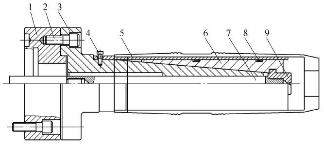
Figure 1-23 Two-layer wrapping fixture implementation structure
1—First flange 2—Screw 3—First clamp body 4—Screw 5—Expansion tile 6—Expansion block 7—First pull core 8—Expansion ring 9—First baffle
Component surface matches fixture
The rear end of the first flange 1 is connected to the main shaft of the machine tool, and the front end is connected to the first clamping body 3 through screws 2. The clamping body is a conical surface with a diameter gradually decreasing from the back to the front. The main shaft drives its forward and backward movement. The first clamp body 3 is equipped with an expansion block 6, the inner surface of the expansion block matches the outer conical surface of the clamp, the outer surface of the expansion block is a cylindrical surface, and the front end of the expansion block 6 is fixedly connected with the first pull core 7 through the first baffle 9, two expansion rings 8 are fixed on the expansion block 6, and expansion tiles 5 are sleeved on the expansion rings 8, and the expansion tiles 5 are connected to the first clamping body 3 through screws 4.
The workpiece is placed on the expansion shoe 5 and positioned closely, the first pull core 7 drives the first baffle 9 to pull the expansion block 6 to move toward the main shaft, and at the same time, the expansion shoe 5 is expanded and tightened by sliding to clamp the workpiece.
The machining accuracy of this fixture can reach 0.07~0.10mm, which is suitable for the semi-finishing process of the shape of a large batch of workpieces with a wall thickness of 7~9mm or the final shape processing process of the workpiece with low precision requirements.
Semi-finished outer diameter
As shown in Figure 1-24, the outer diameter of the semi-finishing turning adopts a CNC machine tool, using a disc spring fixture, through the axial pulling force of the second pull core 4, after the disc spring 5 is deformed by force, the outer diameter of the disc spring is generated. The stable and reliable elastic circumferential deformation of 0.3~0.5mm acts evenly on the surface of the inner cavity of the workpiece to clamp the workpiece. The deformation of the workpiece is small and elastic deformation. The cutting parameters are: cutting speed vc=130~150m/min, feed amount f=0.15~0.2mm/r, and back-cut amount ap=0.5~1mm.
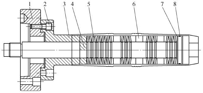
Figure 1-24 Implementation structure of disc spring clamping fixture
1—Second flange 2—Screw 3—Second clamping body 4—Second pull center 5—Disc spring 6—Protective sleeve 7—Second baffle 8—Sealing ring
The disc spring clamp includes a second flange 1, screws 2, a second clamping body 3, a second pull core 4, a disc spring 5, a protective sleeve 6, a second baffle plate 7, and a sealing ring 8.
Reasonable clamping process
One end of the second flange plate 1 is connected with the main shaft of the machine tool, and the other end is connected with the second clamping body 3 through screw 2. In the second clamping body, the second pulling core 4 is installed by sliding fit, and one end of the second pulling core is connected with The main shaft oil cylinder is connected, the other end is connected to the second baffle 7, the sealing ring 8 is installed on the second baffle, the disc spring 5 and the protective sleeve 6 are alternately interspersed on the pull core, and the other end of the second clamping body is connected with the second baffle. between the baffles. The protective sleeve protects the second clamping body and the second pulling core, and at the same time, the clamping position and clamping width of the disc spring can be adjusted to protect the force-bearing area and contact point position of the inner cavity of the thin-walled cylindrical piece. The thickness of the disc spring and the number and size of openings are adjusted by testing according to the position in the fixture. Disc springs are multi-point circumferential contact. Sleeve the thin-walled cylindrical piece on the fixture, the open end is close to the positioning surface of the fixture body, the oil cylinder drives the pull core to make the disc spring clamp the workpiece, complete the clamping, and start processing. After the processing is completed, the workpiece can be removed.
The machining accuracy of the fixture can reach 0.05~0.07mm, and it is suitable for the finishing process of the shape of a large number of workpieces with a wall thickness of more than 6mm, or the semi-finishing of the shape of a high-precision workpiece.
Aging
Artificial aging at 200°C and heat preservation for 24h.
Fine turning shape
Use CNC machine tools or CNC machining centers, and use elastic airbag fixtures. The inflatable airbag itself is elastic, and the airbag tensioning force acts on the thin-walled workpiece evenly. The size of the airbag elastic force can be set with a safety valve. The size is adjusted according to the wall thickness and strength of the thin-walled workpiece, as well as the size of the cutting force. In turning machining, the cutting parameters are: cutting speed vc=150~180m/min, feed rate f=0.1~0.15mm/ r, and the amount of knife on the back ap=0.1~0.2mm.
As shown in Figure 1-25, the elastic airbag clamp includes a third flange 1, a screw 2, a third clamping body 3, an airbag 4, a safety valve 6, a quick release valve 7, a positioning stop ring 8, and a one-way valve One-touch fittings 9.
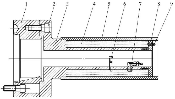
Figure 1-25 Implementation structure of elastic airbag clamp
1—Third flange 2—Screw 3—Third clamp body 4—Airbag 5—Workpiece 6—Safety valve 7—Quick release valve 8—Locating retaining ring 9—One-touch fitting
The third clamping body 3 is fixed on the third flange 1 on the machine tool through screws 2, the airbag 4 is mounted on the third clamping body 3, and each connecting pipe joint of the airbag is put into the corresponding positioning hole of the clamping body, and the positioning The baffle ring 8 is installed on the third clamp body 3, the safety valve 6 and the quick-change valve 7 are installed in the corresponding positioning holes on the third clamp body and are connected with the corresponding pipe joints of the airbag. Pipe joint 9 passes through the positioning hole of the positioning retaining ring and is connected to the airbag tube joint. Check each joint for an air tightness test, and install workpiece 5 on the positioning table of the third clamping body and the positioning surface of the positioning retaining ring. Realize the positioning of the thin-walled workpiece, inflate the airbag through the quick-change pipe joint with a one-way valve, set the air pressure of the airbag through the safety valve, and tighten the workpiece under the elastic force of the airbag after the inflation is completed. Clamping of workpieces, and processing thin-walled workpieces such as steel pipes. Detect the workpiece, adjust the pressure of the airbag, pull the handle of the quick deflation valve after the workpiece is processed, and deflate the airbag. After meeting the requirements of the drawing, unload the workpiece, and start batch processing after passing the inspection.
The machining accuracy of the fixture can reach within 0.02mm, and it is suitable for the shape-finishing process of large quantities of high-precision workpieces such as steel pipes with a wall thickness of 2~5mm.
Inner diameter of fine turning
Put the finished workpiece into the semi-open fixture, the inner hole diameter of the fixture is basically the same as the outer diameter of the workpiece, the conical surface of the locking screw and the inclined surface of the gland are in contact with each other, tighten the screw, compress the workpiece, turn The size of the tightening force should not be too tight. Adjust according to the wall thickness and strength of the thin-walled workpiece and the size of the cutting force, and finish machining the inner hole. The cutting parameters are: cutting speed vc=150~180m/min, feed amount f=0.1~0.15mm/r, and back-cut amount ap=0.1~0.2mm.
As shown in Figure 1-26, the semi-open clamp includes a fourth flange 1, screws 2, a fourth clamping body 3, a positioner 4, a rotating shaft 5, a press cover 6, a locking shaft 7, and a spring 8.
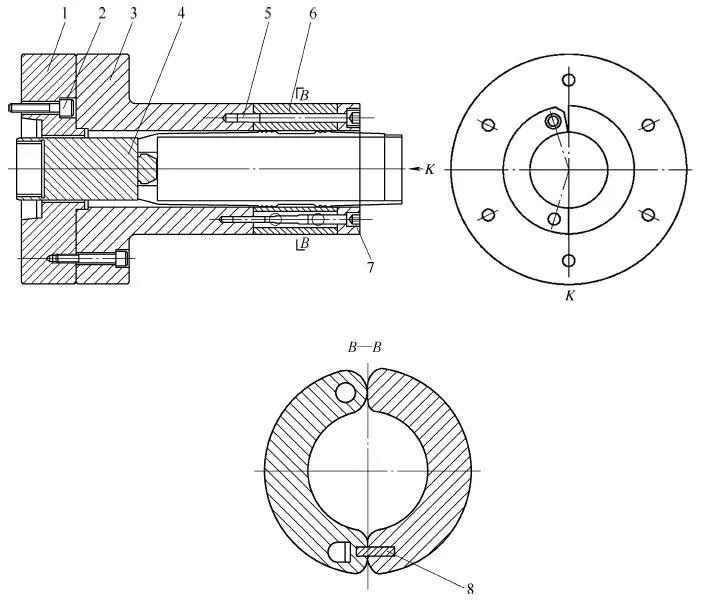
Figure 1-26 Implementation structure of the half-open fixture
1-Fourth flange 2-Screw 3-Fourth clamp body 4-Positioner 5-Rotation shaft 6-Gland 7-Lock shaft 8-Spring
Positioning component
The rear end of the fourth flange 1 is fixed on the machine tool by screws 2, and the front end is fixed with the fourth clamping body 3. The front part of the fourth clamping body 3 is provided with a semicircular arc groove of a certain length. The arc groove is matched and installed in the tool and forms an inner hole with the clamping body to clamp the cylindrical workpiece. The fixed end of the gland is rotatably connected with the clamping body through the rotating shaft 5, and the movable end is locked with the clamping body through the locking shaft 7. Both the fixed end and the movable end are parallel to the central axis, gland 6 is fixed on the clamping body 4 through the rotating shaft 5, and the clearance of the rotating shaft relative to the rotating shaft hole of the gland and the positioning hole of the fourth clamping body is controlled within 0.05mm so that the gland The fourth clamping body can be freely opened and closed through the rotating shaft, and the middle of the locking shaft is provided with a tapered conical surface, which is consistent with the inclined surface of the locking hole on the gland. By tightening the locking shaft, the small taper cone of the locking shaft moves inward and contacts the small taper inclined surface of the locking hole of the gland, pressing the gland to achieve the function of pressing and quenching the thin-walled cylindrical workpiece.
A spring is provided between the end face where the movable end face of the gland and the clamping body meet. After releasing the locking shaft, the gland can be opened. One end of positioner 4 is connected with the spindle of the machine tool, and the other end passes through the flange and is located behind the clamping body. In the center hole of the part, it is used to locate the cylindrical workpiece.
Figures 1-27 is views of the gland from various angles.
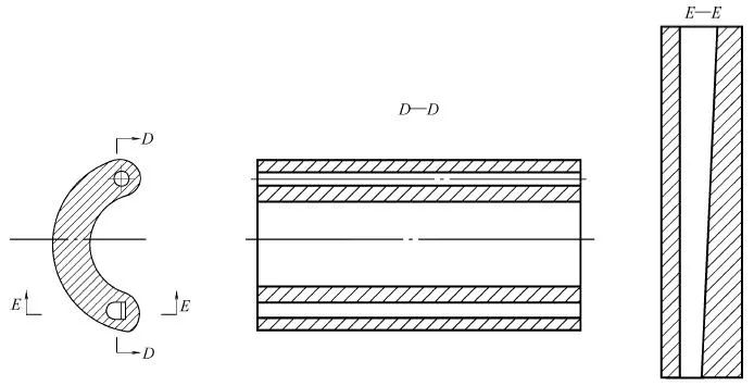
Figure 1-27 Sectional view of the gland
Before use, assemble the whole set of clamps and fix them on the machine tool. Add a thin gasket to the front and rear surfaces of the fourth clamp body and the gland to make a certain gap between the clamp body and the gland. Rotate the locking shaft and carry it out on the machine tool. Overall processing. The positioning hole of the workpiece is clamped by the fixture, and it is processed to the maximum limit size of the outer diameter tolerance of the quenched thin-walled shell and tube workpiece to be clamped, so as to achieve the positioning accuracy and clamping contact area of the workpiece clamped by the fixture. Loosen the locking shaft, and under the action of the spring, open the gland to complete the loading and unloading of thin-walled cylindrical workpieces. The force for tightening the locking shaft is appropriately adjusted according to the cutting force for processing quenched thin-walled shell-and-tube parts.
|
Try Tuofa Now! Tuofa Engineer Support Team - Real human quotes are more accurate than software quotes |
Get a free quote |
Machining accuracy requirements
The machining accuracy and geometric tolerance can reach 0.01~0.03mm, which is suitable for the inner hole finishing process of large-scale and high-precision workpieces with a wall thickness of 5~7mm.
Positioning clamping method
The two-layer wrapping clamp positioning and clamping method are adopted for grinding and positioning the clamping surface under working conditions. The expansion force directly acts on the clamped workpiece, and the clamped thin-walled quenching hardware is easily deformed. When designing the fixture, the positioning and clamping surface of the expansion shoe is used to wrap the second layer of the jacket for absorbing part of the expansion force, so that the clamping force acts more evenly on the positioning and clamping surface of the workpiece. Apply external force in front of the two-layer wrapping clamp to adjust the pull core, so that the expansion tile of the clamp is deformed, which acts on the second layer of the jacket, and produces deformation to reach the working state. In the working state, the clamping surface of the second layer of the jacket is positioned. Grinding is performed until the inner hole of the expanded workpiece is slightly smaller.
After the external force is eliminated, the second layer of the expansion sleeve is deformed and the diameter of the expansion sleeve is reduced. The workpiece processed during use can be easily clamped to the expansion tile. In the process of processing, a two-layer wrapping clamp is used for grinding and positioning the clamping surface under working conditions. The jacket absorbs part of the clamping force so that the clamping force acts evenly on the clamped workpiece, and the deformation is small. The processing quality of the product can be guaranteed.
Because the disc spring is evenly opened, under the action of hydraulic and pneumatic clamping force. The small elastic deformation produced by the disc spring acts evenly on the surface of the clamped workpiece to realize the positioning and clamping of the workpiece. The deformation of the workpiece is small and the positioning accuracy is high.
For tube and shell parts with high precision, small finishing allowance, workpiece wall thickness less than 4mm, and high strength, elastic air bag fixtures are used. The airbag itself is elastic. The generated clamping force acts evenly on the circumferential surface or axial end face of the clamped workpiece, the generated clamping force is less than the deformation force of the workpiece, and the clamping force should be greater than the cutting force.
The clamping meets the precision of the inner bore of the quenching hardware
The tolerance of thin-walled tube and shell parts is small, so the semi-open clamp is used in the processing of the inner hole. Compared with the hydraulic and pneumatic clamp devices, the clamping force of this mechanical semi-open clamp is relatively small and can be adjusted according to the cutting force make adjustments. The size of the clamping and positioning inner hole of the semi-open clamp is fully processed to the maximum limit size of the clamped workpiece in the clamped state. When clamping the workpiece, the clamping area is large and the clamping force acts on the clamped workpiece evenly, and the deformation caused by the clamping is small. It meets the requirements of high-precision thin-walled tube shell quenching hardware inner hole processing.
| Let's Start A New Project Today |
| Get a Free Quote |
Visible effect
The processing technology adopted by Tuofa CNC machining ensures processing accuracy. At different processing stages, by using various fixtures, the positioning and clamping of the thin-walled shell-and-tube quenching hardware are realized, and the deformation problem of the thin-walled shell-and-tube quenching hardware under the action of the clamping force is solved.
 Tel/WeChat:
  Email:
 Home
Home
 41 Questions for CNC Machinist- Necessary Knowledge


