High Strength Bolt: Classification & Process | Guide
 Nov 30,2022

Today's advanced manufacturing represented by large aircraft, large power generation equipment, automobiles, high-speed trains, large ships, and large complete sets of equipment has entered an important development direction. As a result, fasteners will enter an important stage of development. High-strength bolts are used for the connection of important machinery, and repeated installation torques have extremely high requirements for high-strength bolts. Therefore, the quality of its surface condition and thread precision will directly affect the service life and safety of the main engine. In order to improve the coefficient of friction and avoid corrosion, seizure or seizure during use, the technical requirements stipulate that the surface should be treated with nickel-phosphorus plating. The thickness of the coating is guaranteed to be within the range of 0.02-0.03mm, and the coating is uniform, dense, and free of pinholes.
What are high strength bolts
Bolts made of high-strength steel, or bolts that require a large pre-tightening force, can be called high-strength bolts. High-strength bolts are mostly used for the connection of bridges, rails, high-pressure and ultra-high-pressure equipment. The fracture of such bolts is mostly brittle fracture. The high-strength bolts used in ultra-high pressure equipment require a large prestress in order to ensure the sealing of the container.
Basic knowledge
1. According to the strength of the bolt material in the United States, it is divided into the following two types:
a) ASTMA325, A325M, F1852 - minimum tensile strength 120/105Ksi (830Mpa)
b) ASTMA490, A490M, F2280 - minimum tensile strength 150Ksi (1040Mpa)
The suffix "M" is the metric unit; F1852 and F2280 are torsional shear type tension control high-strength bolts.
2. There are Type 1 and Type 3 high-strength bolts in the United States (Type 2 is obsolete). Different types indicate that high-strength bolts use different materials and surface treatments are also different (see Table 2.1 of RCSC High-Strength Bolt Specifications for surface treatment).
Sign of High Strength Bolt Type (RCSC High Strength Bolt Specification 2.3.3)
| Bolt | Type 1 | Type 2 |
| A325 | Medium carbon steel | Corrosion resistant steel |
| A490 | Alloy steel | Corrosion resistant steel |
Sign of High Strength Bolt Type (RCSC High Strength Bolt Specification 2.3.3)
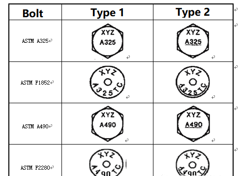
3. Large hexagon head high-strength bolts and torsional-shear type tension control high-strength bolts are only different in installation methods, and their other performances are exactly the same.
4. High Strength Bolt Joint Types (Section 4 of RCSC High Strength Bolt Specifications)
a) ST— Moderately tightened connection nodes, the connection surface does not need to be treated.
b) SC—Friction type connection joint, the connection surface requires treatment.
c) PT—Applies pretension to the connection node, and the connection surface does not need to be treated.
5. Pressure type connection and friction type connection. The same high-strength bolts are used, but the concept of bearing capacity is different, and the requirements for the surface of the steel are different. The pressure-bearing connection is only suitable for standard holes, short slotted holes and long slotted holes where the load is perpendicular to the direction of the slotted hole; the friction type connection is suitable for standard holes, oversized holes, short slotted holes and long slotted holes.
6. The meaning of high strength bolt suffix:
N: For pressure-containing connections, high-strength bolt threads are in the shear plane.
Example: A490-N
X: For pressure-containing connections, high-strength bolt threads are outside the shear plane.
TC: Torsional Shear Type Tension Control High Strength Bolts
Example: A325-TC
T: A325 bolts can be fully threaded when the length is ≤4d, which is expressed as A325T.
Moderately tighten the connection node
A moderately tightened joint is a state in which all bolts within the joint are fully tightened so that the connecting plates within the joint are in tight contact and prevent the nuts from being unscrewed without the use of a wrench. (RCSC Specification for High Strength Bolts - 2009 8.1).
When installing, you can use an impact wrench for a few impacts, or a worker can use an ordinary wrench to tighten it with full force. (RISC Specification for High Strength Bolts - 2004 8.1).
Inch and metric series of American high-strength bolts
American High Strength Bolts can be expressed in imperial or metric units. Imperial units and metric units are not completely corresponding. The diameter, thread pitch, hole size, nut shape, washer thickness, and bolt length selection of high-strength bolts are all different. RCSC high-strength bolt specifications are imperial units and metric units Data can be found in AISC 360 Chapter J Connection Design and other specialized metric standards.
1. Inch series and metric series of American high-strength bolt diameters
Imperial units (in) 1/2 5/8 3/4 7/8 1 1-1/8 1-1/4 1-3/8 1-1/2
Metric units (mm) M16 M20 M22 M24 M27 M30 M36
2. The opening size of American high-strength bolts
American high-strength bolt openings are the same whether they are pressure-bearing or friction-type connections.
Opening size (in) (AISC 360 Table J3.3)
| Bolt diameter | Aperture | |||||
| Standard hole | Oversize hole | Short slot (W x L) | Long slot hole (W x L) | |||
| 1/2 | 9/16 | 5/8 | 9/16 x 11/16 | 9/16 x 1-1/4 | ||
| 5/8 | 11/16 | 13/16 | 11/16 x 7/8 | 11/16 x 1-9/16 | ||
| 3/4 | 13/16 | 15/16 | 13/16 x 1 | 13/16 x 1-7/8 | ||
| 7/8 | 15/16 | 1-1/16 | 15/16 x 1-1/8 | 15/16 x 2-3/16 | ||
| 1 | 1-1/16 | 1-1/4 | 1-1/16 x 1-5/16 | 1-1/16 x 2-1/2 | ||
| ≥1-1/8 | d+1/16 | d+5/16 | (d+1/16) x (d+3/8) | (d+1/16) x (2.5 x d) | ||
Opening size (mm) (AISC 360 Table J3.3)
| Bolt diameter | Aperture | |||||
| Standard hole | Oversize hole | Short slot (W x L) | Long slot hole (W x L) | |||
| M16 | 18 | 20 | 18 x 22 | 18 x 40 | ||
| M20 | 22 | 24 | 22 x 26 | 22 x 50 | ||
| M22 | 24 | 28 | 24 x 30 | 24 x 55 | ||
| M24 | 27 | 30 | 27 x 32 | 27 x 60 | ||
| M27 | 30 | 35 | 130 x 37 | 30 x 67 | ||
| M30 | 33 | 38 | 33 x 40 | 33 x 75 | ||
| ≥M36 | d+3 | d+8 | (d+3) x (d+10) | (d+3) x 2.5d | ||
3. Dimensions of bolts and nuts
Thread length and pitch of high-strength bolts A325 and A490 and thickness of A563 nuts (in)
| Diameter | 1/2 | 5/8 | 3/4 | 7/8 | 1 | 1-1/8 | 1-1/4 | 1-3/8 | 1-1/2 |
| Thread length | 1 | 1-1/4 | 1-3/8 | 1-1/2 | 1-3/4 | 2 | 2 | 2-1/4 | 2-1/4 |
| Thread pitch (in) | 13 | 11 | 10 | 9 | 8 | 7 | 7 | 6 | 6 |
| Nut thickness | 31/64 | 39/64 | 47/64 | 56/64 | 63/64 | 1-7/64 | 1-7/32 | 1-11/32 | 1-15/32 |
When looking for detailed dimensions of high strength bolts and nuts, see ASME B18.2.6 and ASME B18.2.6M.
4. Washer thickness
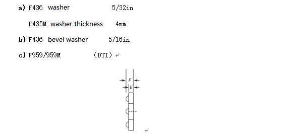
F959M Force Washer Thickness (mm) (ASME B18.2.6M Table 5)
| Bolt Diameter | 1/2 | 5/8 | 3/4 | 7/8 | 1 | 1-1/8 | 1-1/4 | 1-3/8 | 1-1/2 |
| E | 0.104 | 0.126 | 0.126 | 0.142 | 0.158 | 0.158 | 0.158 | 0.158 | 0.158 |
| F | 0.180 | 0.220 | 0.230 | 0.240 | 0.270 | 0.270 | 0.270 | 0.270 | 0.270 |
Use of Washers
1. Moderately tighten the joint (Sung-Tightened Joint)
a) Inclined surface: When the inclination exceeds 1:20, use ASTM F436 oblique washers.
b) Slots: Use ASTM F436 washers or 5/16in thick common steel shims to block the slots.
c) Except for items a) and b), no gaskets are used.
2. Pre-tightening bolts and friction type connection joints
Gaskets are not required except for the following
a) When A490 or F2280 bolts are used and the minimum yield strength of the connecting material is less than 40Ksi (276N/mm), two F436 washers are required for large hexagon head bolts, and one F436 washer is required for torsional shear tension control bolts.
b) When using a calibration wrench, an F436 washer is required to be placed under the rotating member.
c) Torsional shear bolts need to put an F436 washer under the nut;
d) Use the force indicator washer (DTI) as shown in the following figure:
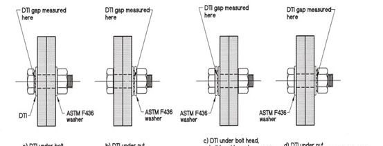
Turn the nut: the force washer is placed on the bolt head, and the washer is placed on the nut (a)
Turn the nut: the force washer is placed at the nut, and the washer is placed between the nut and the force washer
Turn the nut: the indicator washer is placed under the bolt head, and the washer is placed between the bolt head and the indicator washer
Turn the nut: place the force washer under the nut and the washer under the bolt head (figure d)
e) Gaskets for oversized holes and slotted holes (RCSC High Strength Bolt Specification Table 6.1)
ASTM F436 gasket plus 3/8in thick steel plate gasket or continuous steel plate of the same grade as the structure
Oversized hole and slotted hole spacers should be sized to completely cover the hole.
| Specifications | Diameter (in) | Oversize hole and short slot hole | Long slotted hole |
|
A325 F1852 |
1/2 – 1-1/2 | ASTM F436 | 5/16in thick steel plate gasket or continuous steel plate |
|
A490 F2280 |
≤1 | ||
| >1 | ASTM F436 5/16in thick | ASTM F436 gasket plus 3/8in thick steel plate gasket of the same grade as the structure or continuous steel plate |
Selection of the length of high-strength bolts
The length of the bolt, when fully installed in place, the end of the bolt should exceed the outer surface of the nut, at least flush (2.3.2 of the RCSC high-strength bolt specification). Under normal circumstances, 2-3 threads should be exposed.
1. Length selection of high-strength bolts in imperial system (Article 2.3.3 of RCSC High-strength Bolt Specifications)
The length of high-strength bolts using imperial units should be the grip length (the total thickness of the connected components), plus the additional length, which has fully considered the manufacturing tolerance and provided enough threads for the installation of large hex nuts.
For each F436 flat washer, the bolt length shall be increased by 5/32in, and for each F436 slanted washer, the bolt length shall be increased by 5/16in. When using the F959 force indicator washer, the thickness of the force indicator washer shall be added.
The length of high-strength bolts determined according to the above principles should be adjusted to the next 1/4in length, and when the bolt length exceeds 6in, the length should be adjusted to the next 1/2in length.
Bolt additional length (excluding washers) (in) (RCSC High Strength Bolt Specification Table C2.2)
| Bolt diameter | 1/2 | 5/8 | 3/4 | 7/8 | 1 | 1-1/8 | 1-1/4 | 1-3/8 | 1-1/2 |
| Additional length | 11/16 | 7/8 | 1 | 1-1/8 | 1-1/4 | 1-1/2 | 1-5/8 | 1-3/4 | 1-7/8 |
2. Selection of the length of metric high-strength bolts
American standards do not give additional lengths using metric units, and in our experience, the length of a high strength bolt should be the grip length (total thickness of the connected member) plus the thickness of the washer (including the force washer), plus the nut Thickness, plus thread 2-3 buckles, we recommend that the high-strength bolt length determined according to the above principles be rounded to 3, and the mantissa of the bolt length adjusted to 5 or 0. (The U.S. stipulates that when the bolt length is ≤100mm, increase by 5mm, when the length is >100mm, increase by 10mm, and we recommend that when the length is >100mm, also increase by 5mm.)
The bolt length can be determined using the table below, and the thickness of the indicator washer should be added if the indicator washer is used.
Bolt additional length M (mm):
| Bolt diameter | Washer not included Additional length | Add a flat washer for additional length | Add two flat washers for additional length |
| M16 | 23 | 27 | 31 |
| M20 | 27.5 | 31.5 | 35.5 |
| M22 | 30.5 | 34.5 | 38.5 |
| M24 | 33 | 37 | 41 |
| M27 | 36 | 40 | 44 |
| M30 | 40.5 | 44.5 | 48.5 |
| M36 | 48 | 52 | 56 |
Hole distance and edge distance regulations
1. Minimum hole distance (AISC 360 J3.3)
The hole center distance should not be less than 2-2/3 d (d is the diameter of the bolt), generally 3d.
2. Minimum Margins
For standard holes, in any direction shall not be smaller than specified in the table below, or calculated according to AISC 360 J3.10.
For oversized holes and slotted holes, AISC 360 J3.4 shall be followed.
Minimum Margins (in) (AISC 360 Table J3.4)
Note: 1-1/4in. is allowed for beam end connection angle steel and shear end plate.
| Bolt diameter | Cut edge | Rolled Edge or Flame Cut |
| 1/2 | 7/8 | 3/4 |
| 5/8 | 1-1/8 | 7/8 |
| 3/4 | 1-1/4 | 1 |
| 7/8 | 1-1/2 | 1-1/8 |
| 1 | 1-3/4 | 1-1/4 |
| 1-1/8 | 2 | 1-1/2 |
| 1-1/4 | 1-3/4 | 1-5/8 |
| Over 1-1/4 | 1-3/4 x d | 1-1/4 x d |
3. Maximum hole distance and side distance (AISC 360 J3.5)
12 times the thickness of the connecting plate from the center of the hole to any near edge, but not exceeding 6 inches (150mm)
The longitudinal spacing of connectors is limited as follows:
a) painted or unpainted but not subject to atmospheric corrosion, spaced not more than 24 times the thickness of the thinner plate or 12 inches (305 mm);
b) Unpainted weathering steel subject to atmospheric corrosion, spaced not to exceed 14 times the thickness of the thinner plate or 7 inches (180 mm);
Anti-slip coefficient (RCSC high-strength bolt specification 5.4.1)
The surface of American steel is divided into three grades: A, B, and C
Class A: Remove rusted and uncoated steel surfaces, or surfaces with Class A coatings after blasting. =0.33
Class B: Uncoated steel surface after blasting treatment, or surface with Class B coating after blasting treatment. =0.50
Grade C: Rough hot-dip galvanized surface. =0.35
Friction-type connection pass coefficient(RCSC high-strength bolt specification 5.4.1)
1. 1 for standard holes.
2. 0.85 for oversized holes and short slotted holes.
3. The load vertical slot hole is 0.7.
4. The load along the long slot is 0.6.
Pretightening force of high-strength bolts
Pretightening force of high-strength bolt (Kips) (AISC 360 Table J3.1)
| Bolt diameter | A325 | A490 |
| 1/2 | 12 | 15 |
| 5/8 | 19 | 24 |
| 3/4 | 28 | 35 |
| 7/8 | 39 | 49 |
| 1 | 51 | 64 |
| 1-1/8 | 56 | 80 |
| 1-1/4 | 71 | 102 |
| 1-3/8 | 85 | 121 |
| 1-1/2 | 103 | 148 |
High-strength bolt connection
High-strength bolt connections can be divided into three types according to their stress conditions: friction connection, pressure-bearing connection and tension connection. Among them, the first two connections mainly bear shear force, and the third mainly bears tension force. Friction type connection is a widely used connection form at present.
Friction-type connections rely on the friction between the connecting plates to carry the load. The bolt closed hole in the connection is not under pressure, and the screw is not sheared. This kind of connection stress transfers smoothly, and the joint rigidity is good. The high-strength bolt connection usually referred to is this kind of friction connection. In high-strength bolted friction connections, the friction force between the plates is just about to be overcome as the ultimate state of bearing capacity.
The bearing capacity limit state of the pressure-bearing connection is that the friction is overcome, the gusset plate is relatively slipped, and the hole wall is under pressure and the bolt is sheared. This kind of connection will produce a certain sliding deformation after the friction force is overcome, so its application is limited, but the bearing capacity of this connection is higher than that of high-strength bolt friction connection, and the economy is good.
Tension-type connection: When the external force is consistent with the axial force of the high-strength bolt, such high-strength bolt connections as flange connection, T-type connection, and bolt-ball joint connection are called tension-type connections. The characteristic of this connection is that the external force is balanced with the pressure generated between the connecting parts by the pre-tightening force of high-strength bolts.
High-strength bolts are high-strength bolts and are a standard part. High-strength bolt connection is a new type of steel structure connection after riveting connection, and it is the main means of steel structure connection at present. The full name of high-strength bolts in production is called high-strength bolt connection pair, and it is generally not referred to as high-strength bolts for short.
Types and specifications of high-strength bolts
1. Distinguish according to appearance
High-strength bolts can be divided into torsional shear-type high-strength bolts and large hexagon head high-strength bolts in terms of appearance.
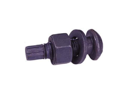
Torsional shear high-strength bolts
Torsional shear type high-strength bolts for steel structures A bolt connection pair is a bolt, a nut and a washer, which is suitable for friction-type connection steel structures.
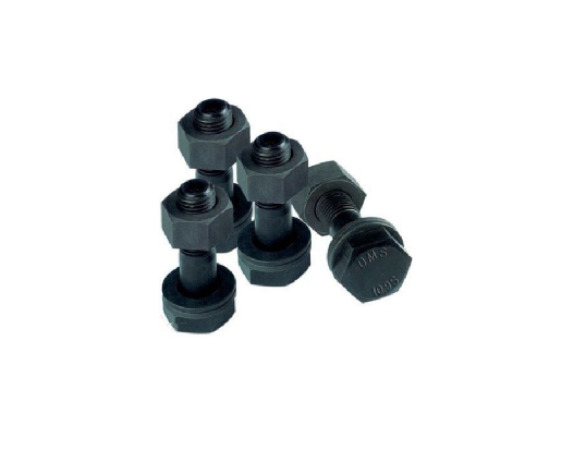
Large hexagon head high-strength bolts
The high-strength large hexagonal head bolts for steel structures are coarse-threaded ordinary threads, which are divided into two grades: 8.8S and 10.9S. One connection pair consists of one bolt, one nut and two washers. The high-strength bolt connection pair should be manufactured in the same batch to ensure the stability of the torque coefficient. The average torque coefficient of the same batch connection pair is 0.110-0.150, and the standard deviation of the torque coefficient should not be greater than 0.010.
Large hexagonal high-strength bolts belong to the high-strength grade of ordinary screws, while torsional shear high-strength bolts are improved types of large hexagonal high-strength bolts for better construction.
2. According to the performance level
According to the performance grade of high-strength bolts, it is divided into: 8.8, 10.9 and 12.9. At present, the large hexagonal high-strength bolts used in our country are: 8.8 grades and 10.9 grades, and the torsional shear type high-strength bolts are only 10.9 grades. Among them, there are only large hexagonal high-strength bolts in grade 8.8. In the marking method, the number before the decimal point indicates the tensile strength after heat treatment; the number after the decimal point indicates the yield ratio, that is, the ratio of the measured value of yield strength to the measured value of ultimate tensile strength. . Grade 8.8 means that the tensile strength of the bolt shaft is not less than 800MPa, and the yield ratio is 0.8; Grade 10.9 means that the tensile strength of the bolt shaft is not less than 1000MPa, and the yield ratio is 0.9.
3. According to the force division
In terms of shear design, high-strength bolts are divided into: high-strength bolt pressure-bearing type and high-strength bolt friction type according to the force state requirements.
For the high-strength bolt friction type, the sliding between the plates is regarded as the limit state of the bearing capacity.
The connecting parts are not allowed to slide each other, the deformation is small, and the bearing capacity is small. Process guarantee measures: sandblasting, so that m=0.3~0.55.
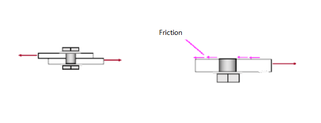
Schematic diagram of high-strength bolt friction force
The high-strength bolt bearing type uses connection failure as the limit state of bearing capacity.
Mutual sliding is allowed between the connectors. At the beginning of the force transmission, there is no slip between the dynamic connectors under the standard load, and the shear force is transmitted jointly by the friction force and the shear resistance of the screw. However, when the load is large, there is a large plastic deformation between the connectors. When it is close to failure, there is relative sliding between the connecting parts, and the friction only plays a role in delaying the sliding. The shear force is transmitted by the screw, which has the same characteristics as ordinary bolts. Therefore, there are the same limit states as ordinary bolts-the bolt is sheared, the hole wall is crushed, and the member is broken. Large deformation, not suitable for connection under dynamic load.
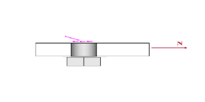
Schematic diagram of high-strength bolts bearing pressure
The bolt connection of the main components of the building structure is generally connected by high-strength bolts. Ordinary bolts can be reused, but high-strength bolts cannot be reused.
High-strength bolt connection proces
1. General provisions
(1) The high-strength bolt connection should be inspected and re-inspected for the connection pair and the friction surface before the connection, and the installation can only be carried out after passing the test.
(2) For each connecting joint, temporary bolts or punching nails should be used for positioning first. In order to prevent changes in the torque coefficient caused by damaged threads, it is strictly forbidden to use high-strength bolts as temporary bolts. For a joint, the number of temporary bolts and punching nails shall be calculated and determined according to the load that the joint may bear, and shall comply with the following regulations:
① Not less than 1/3 of the total number of mounting bolts;
② Not less than two temporary bolts;
③The number of nail penetration should not be greater than 30% of the temporary bolts.
(3) The penetration of high-strength bolts should be carried out after adjusting the center position of the structure, and the penetration direction should be based on the convenience of construction, and strive to be consistent; when installing, pay attention to the front and back of the washer, that is: one side of the nut with a round table The side should face the chamfered side of the washer; for the washer on the side of the large hexagon head high-strength bolt connection pair close to the screw head, the chamfered side faces the bolt head.
(4) The installation of high-strength bolts should be able to freely penetrate the hole, and forced penetration is strictly prohibited. If it cannot be freely penetrated, the hole should be trimmed with a reamer; the maximum diameter of the corrected hole should be less than 1.2 times the diameter of the bolt. When repairing the hole, in order to prevent iron filings from falling into the seam of the plate stack, all the bolts around the hole should be tightened before reaming, so that the plate stack is tightly bonded before proceeding, and gas cutting and reaming are strictly prohibited.
(5) In the high-strength bolt connection, the hole diameter of the connecting steel plate is slightly larger than the bolt diameter, and the drilling method must be adopted. The surface of the steel plate after drilling should be flat, and there should be no flash and burr on the edge of the hole, and there should be no welding spatter on the surface of the connecting plate , oil pollution, etc. Table of allowable deviation of bolt hole diameter is as follows:
|
Name |
Diameter and allowable deviation (mm) |
|||||||
|
Bolt |
Diameter |
12 |
16 |
20 |
(22) |
24 |
(27) |
30 |
|
|
Deviation |
±0.43 |
±0.52 |
±0.84 |
||||
|
Bolt hole |
Diameter |
13.5 |
17.5 |
22 |
(24) |
26 |
(30) |
33 |
|
|
Deviation |
±0.43 0 |
±0.52 0 |
±0.84 0 |
||||
|
Roundness (difference between largest and smallest diameter) |
1.00 |
1.50 |
||||||
|
Inclination of centerline |
It shall not be greater than 3% of the plate thickness, and the single layer plate shall not be greater than 2.0mm, and the multilayer plate stack combination shall not be greater than 3.0mm |
|||||||
(6) In addition to meeting the requirements of Table 2.10, the hole distance and side distance of the bolt holes of the high-strength bolt connection plate should also consider the operable space of special construction tools. The operable space of bolts with general specifications is shown in the figure and table below:
Operational Space Dimensions of Construction Equipment
|
Wrench type |
Latest size (mm) |
Diagram |
||
|
a |
b |
|
||
|
Manual fixed torque wrench |
1.5d0 and no less than 45 |
140+c |
||
|
Torsion shear type electric wrench |
65 |
530+c |
||
|
Large hexagonal electric wrench |
Wrench M24 |
50 |
450+c |
|
|
Above M24 |
60 |
500+c |
||
When the distance from the center of the gauge to the edge of the component (i.e. a in the figure) does not meet the requirements, and the value b has enough space, it may be considered to use an extended sleeve for screwing. At this time, the diameter of the sleeve head is generally the nut diagonal Add 10mm to the line size.
The permissible deviation of the bolt hole distance of the high-strength bolt connection plate is shown in the following table:
|
Grouping |
Project |
Bolt hole spacing(mm) |
|||||
|
<500 |
500~1200 |
1200~3000 |
>3000 |
||||
|
1 2 |
Between any two holes in the same group |
Allowable deviation |
±1.0 ±1.2 |
±1.2 ±1.5 |
---- ±2.0 |
---- ±3.0 |
|
Note: The grouping of holes stipulates:
1. In the node, all the connecting holes where the connecting plate is connected with a bar are divided into one group;
2. Holes at the joints: universal joints --- the holes on half of the splicing board are a group; stepped joints --- the holes between the two joints are a group;
3. The connection holes between two adjacent nodes or joints are a group, but the holes referred to in 1 and 2 are not included;
4. On the flange of the flexural member, the holes within each 1m length form a group.
| Let's Start A New Project Today |
| Get a Free Quote |
Large hexagon head high-strength bolt connection process
(1) Torque coefficient of large hexagon head high-strength bolt connection pair
For the large hexagonal head high-strength bolt connection pair, when the bolt is tightened, there is a corresponding relationship between the torque value M applied to the nut and the axial tightening force (axial force) P of the introduced bolt:
M = K·D·P
In the formula: D ---- bolt nominal diameter, mm;
P ---- bolt axial force, kN;
M----Torque value applied to the nut, kN m;
K---torque coefficient
The torque coefficient K is related to the following factors:
① The average radius and friction coefficient value of the contact surface between the nut and the washer;
②Thread form, pitch and friction coefficient value between thread contact surfaces;
③ Surface treatment and damage of threads in bolts and nuts, etc.
The torque coefficient K of the high-strength bolt connection pair is the main index to measure the quality of the high-strength bolt. The torque coefficient is supplied. The average value of the torque coefficient of the same batch of connection pairs is 0.110~0.150 (grade 10.9), and its standard deviation should be less than or equal to 0.010. Before installation and use, it must be re-inspected according to the supply batch.
The large hexagon head high-strength bolt connection pair should be inspected and re-inspected according to the batch. The so-called batch refers to: the same performance grade, material, furnace number, thread specification, and length (when the bolt length is ≤100mm, the length difference is ≤15mm, and the bolt When the length is >100mm, the difference in length is ≤20mm, which can be regarded as the same length), bolts with mechanical processing, heat treatment process, and surface treatment process belong to the same batch; bolts with the same performance grade, material, furnace number, thread specification, mechanical processing, heat treatment process, The nuts of the surface treatment process belong to the same batch; the washers of the same performance grade, material, furnace number, thread specification, machining, heat treatment process, and surface treatment process belong to the same batch; the connection pairs composed of the same batch of bolts, nuts, and washers respectively are The same batch connection vice.
(2) Torque method construction
For the large hexagon head high-strength bolt connection pair, when the torque coefficient K is determined, since the axial force (pretension) P of the bolt is specified by the design, the torque value M that should be applied by the bolt can be easily calculated and determined, according to Calculate the determined construction torque value, and use a torque wrench (manual, electric, pneumatic) to perform final tightening according to the construction torque value, which is the principle of the torque method.
When determining the axial force P of the bolt, it should be based on the design pre-tension value. Generally, 10% of the bolt construction pre-tension loss is considered, that is, the bolt construction pre-tension (axial force) P is 1.1 times the design pre-tension value, as shown in the following table is the P value of the pre-tension force (axial force) of the large hexagonal high-strength bolt.
Construction pretension of high-strength large hexagon head bolts (kN)
|
Bolt performance grade |
Bolt nominal diameter d (mm) |
||||||
|
|
M12 |
M16 |
M20 |
M22 |
M24 |
M27 |
M30 |
|
Level 8.8 |
50 |
90 |
140 |
165 |
195 |
255 |
310 |
|
Level 10.9 |
60 |
110 |
170 |
210 |
250 |
320 |
390 |
The torque coefficient of the bolt is easy to change during storage and use, so the torque coefficient is generally re-inspected before installation on the construction site. After the re-inspection is passed, the construction torque is determined according to the re-inspection result, and the construction is arranged accordingly.
The bolts, nuts and washers used for the torque coefficient test shall be randomly selected from the same batch of bolt pairs, and generally 5 to 10 sets shall be taken according to the batch size (because the bolts that have passed the torque coefficient test can still be used in engineering, if conditions permit, the sample More can be selected to better reflect the torque coefficient of the batch of bolts), the test state should be the same as the bolt use state, and the sample is not allowed to be reused. The torque coefficient re-inspection shall be carried out in a qualified testing unit recognized by the state, and the axial force gauge and torque wrench used in the test shall be certified by metrology.
Before final tightening by torque method, initial tightening should be performed first, and retightening is required for large joints with many bolts. The purpose of the initial screwing is to make the contact surface close, and the bolts "tighten". Generally, the initial tightening torque of bolts of commonly used specifications (M20, M22, M24) is 200-300N.m, and the axial force of the bolts can reach 10-50kN. In actual operation, an operator can use an ordinary wrench to use his own hand force Just tighten it.
Generally speaking, the order of initial screwing, re-tightening and final screwing is symmetrical from the middle to both sides or around. The initial screwing and final screwing bolts should be marked differently to avoid safety hazards such as missed screwing and over-tightening. It is also convenient for inspectors to check the fastening quality.
3. Corner construction
Due to the discreteness of the torque coefficient, especially the poor manufacturing quality and construction management of the bolts, the torque coefficient will exceed the standard value (average value and coefficient of variation). In this case, the torque method is used for construction, that is, the torque value is used to control the bolt axial force. method will have a large error. In order to solve this problem, the corner method of construction was introduced. The rotation angle method is a method to control the axial force of the bolt by controlling the elastic elongation of the screw by the rotation angle of the nut.
The experimental results show that after the initial screwing of the bolt, the rotation angle of the nut corresponds to the axial force of the bolt, and when the bolt is tensioned within the elastic range, the relationship between the two is linear. According to this linear relationship, after determining the construction pretension of the bolt (generally 1.1 times the design pretension), it is easy to obtain the rotation angle of the nut, and the construction operator can fasten the construction according to this rotation angle, which can meet the requirements of the design. This is the basic principle of corner method construction.
The construction of the high-strength bolt angle method is divided into two steps: initial tightening and final tightening (re-tightening is added if necessary), and the requirements for the initial tightening are stricter than those of the torque method. This is because there will be a gap between the connecting plates. At first, the rotation angle of the nut is mostly consumed by the gap between the plates, and the relationship between the rotation angle and the axial force of the bolt is unstable; the purpose of the initial screwing is to eliminate the influence of the plate gap and create a roughly consistent basis for the final screwing.
Corner construction has a history of more than 40 years in China, but there is no standard for the size of the initial tightening torque, and each project is determined according to the specific situation. Generally speaking, for commonly used bolts (M20, M22, M24), the initial tightening torque is set at 200-300N.m, which is more appropriate. The final screwing is based on the initial screwing, and then the nut is turned to a certain angle, so that the axial force of the bolt reaches the pre-tensioning force of the construction. The figure below is a schematic diagram of the construction of the corner method.
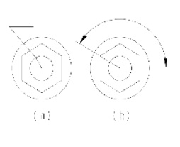
Corner construction method
The construction sequence of the corner method is as follows:
Initial tightening: Use a fixed torque wrench to tighten the nuts sequentially from the center of the bolt group outwards.
Initial tightening inspection: Generally, the percussion method is adopted, that is, a small hammer is used to check one by one, the purpose is to prevent the bolts from being screwed.
Marking: After the initial screwing, mark the bolts one by one, as shown in the figure above
Final screwing: Use a special wrench to rotate the nut at a rated angle, as shown in the figure above, so the sequence of tightening the bolt group is the same as the initial screwing
Final tightening inspection: check whether the rotation angle of the nut meets the requirements one by one after the final tightening of the bolts, and use a protractor to check the relative rotation angle between the bolt and the line on the nut.
Marking: Mark the final screwed bolts with different color pens to prevent leakage and re-tightening, and check by the quality inspector.
The tools used in the final screwing currently include pneumatic wrench, electric wrench, electric fixed-angle wrench and manual wrench, etc. The general way for wrenches to control the angle of the nut is to mark the angle of rotation on the sleeve, so that when the sleeve is placed on the nut Finally, use a pen to mark the starting position of the angle on the sleeve on the steel plate. After turning on the machine, wait until the end line of the angle of the sleeve coincides with the mark on the steel plate, and the final screwing is completed. At this time, the rotation angle of the sleeve is the angle of rotation of the nut. When using a fixed-rotation-angle wrench, the nut rotation angle is controlled by the wrench, and the wrench automatically stops when the specified angle is reached. In order to ensure the accuracy of the final screwing angle, care should be taken to prevent the co-rotation of the bolt and the nut when screwing. For this reason, someone should cooperate to block the screw head on one side of the screw head.
The rotation angle of the nut should be re-inspected before construction. The re-inspection procedure is the same as the torque method construction, that is, the bolts, nuts, and washers for re-inspection should be randomly selected from the same batch of bolt pairs, and generally 5 to 10 sets are taken according to the batch size. , the test state should be the same as the bolt use state, and the sample is not allowed to be reused. The re-inspection of the rotation angle shall be carried out in a qualified inspection unit recognized by the state, and the axial force meter, wrench, protractor and other instruments used in the test shall be certified by metrology.
|
Try Tuofa Now! Tuofa Engineer Support Team - Real human quotes are more accurate than software quotes |
Get a free quote |
China Shenzhen Tuofa CNC Machining Solutions
Whether you need to customize the bolt or sheet metal manufacturing service in the shortest time, from the complex geometric structure or the final use of products, Tufa CNC machining manufacturers are able to show every process and detail, and immediately recognize your concept. Our team manages more than 50 3, 4 and 5 axis CNC partsmanufacturers, and supplies more than 50 materials and 20 surface treatments, realizing a certain rapid turnover, as well as high-quality one-time prototype and batch manufacturing component services.
At tuofa-cncmachining.com, everyone can find inspiration for rapid prototyping and parts manufacturing on the website, and carry out your customized projects to obtain metal and plastic parts. Tuofer Precision CNC Machining Workshop can give you a free quotation today, just contact info@tuofa-cncmachining.com Our engineer support team will reply to you more quickly and professionally, which is more efficient and accurate than the robots in the same industry.
 Tel/WeChat:
  Email:
 Home
Home
 Authoritative Design Process of Plastic Parts - Worth Collecting!


