Aluminum: 4 Welding Methods & 12 Welding Defects
 Dec 14,2022

Aluminum alloy is widely used in industrial products because it has good physical properties. Almost all kinds of welding methods can be used to weld aluminum and aluminum alloys, but aluminum and aluminum alloys have different adaptability to various welding methods. Each welding method has its own application.
Due to improper selection of welding methods and welding process parameters, aluminum alloy parts are severely deformed after welding, or due to defects such as weld pores, slag inclusions, and incomplete penetration, weld metal cracks or loose materials have seriously affected product quality. and performance. Tuofa CNC machining will take you to analyze the 4 welding methods of aluminum alloy and the precautions.
Aluminum Alloy Performance Overview
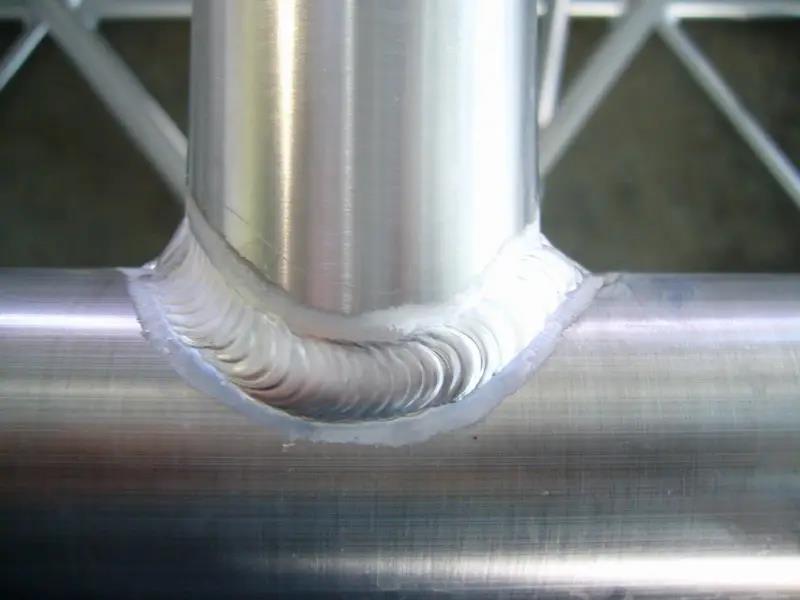
Aluminum is a very light metal material with a density of only 2.7g/cm3, which is about 36% of the density of steel. Aluminum alloy is used to manufacture mechanical parts, which can significantly reduce weight and achieve the effects of light weight, energy saving and emission reduction.
The specific strength and specific stiffness of aluminum alloy are higher than 45 steel and ABS plastic. The use of aluminum alloy materials is conducive to the manufacture of integral components with high rigidity requirements.
Aluminum alloy has excellent thermal conductivity, electrical conductivity and corrosion resistance. The performance parameters of A380 aluminum alloy and other materials are shown in Table 1.
Aluminum alloy has good machinability and recyclability. If it is assumed that the cutting resistance coefficient of the most easily cut magnesium alloy is 1, the cutting resistance of other metals is shown in Table. It can be seen that the cutting resistance of aluminum alloy is less than that of copper, iron and other materials, and the cutting process is relatively easy.
|
Materials |
Density g/cm³ |
Melting point ℃ |
Tensile strength /MPa |
Specific strength |
Yield Strength /MPa |
Elongation % |
Elastic Modulus /GPa |
Specific stiffness |
Thermal Conductivity W/(m·K) |
Damping factor |
|
A380 |
2.7 |
595 |
315 |
116 |
160 |
3 |
71 |
25.9 |
100 |
5 |
|
AZ91D |
1.81 |
596 |
250 |
138 |
160 |
7 |
45 |
25.86 |
54 |
50 |
|
45 steel |
7.86 |
1520 |
517 |
80 |
400 |
22 |
200 |
24.3 |
42 |
15 |
|
ABS |
1.03 |
90 |
96 |
93 |
|
60 |
|
|
|
|
Is Aluminum Welding Difficult?
Aluminum is a soft and very malleable metal. It is less strong for most structures. To improve the strength of aluminum, it is necessary to add alloying elements, with copper, silicon, manganese, magnesium, and zinc as the main addition elements, which play a solid solution strengthening role. Aluminum and its alloys are widely used in many industries.
The welding of aluminum and aluminum alloy is more difficult than that of low carbon steel, and its welding characteristics are different from those of low carbon steel. The specific performance is as follows:
1. The mechanical properties of welded joints soften and the corrosion resistance decreases.
2. The chemical activity is very strong, and the refractory oxide film is easily formed on the surface.
3. Strong thermal conductivity, it is easy to cause insolubility during welding.
4. Defects such as pores, cracks, undercuts, slag inclusions and poor weld formation are prone to occur.
5. The coefficient of linear expansion is large (about 2 times that of low carbon steel), and it is easy to produce warping deformation during welding.
6. The thermal conductivity is large (about 5 times that of low-carbon steel), and at the same welding speed, the heat input is 2 to 4 times larger than that of welded steel.
Classification of Auminum Alloy Welding Technology
With the expansion of the application range of aluminum alloys, more and more problems are highlighted. With the progress of research, the welding technology of aluminum alloy has been greatly developed. At present, there are mainly tungsten argon arc welding (TIG), molten inert gas welding (MIG), laser welding (LBW), friction stir welding (FSW) Wait.
Gas Tungsten Arc Welding
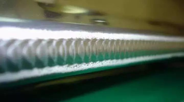
Tungsten Inert Gas Welding (TIG) is a typical inert gas shielded welding and is the most commonly used welding method. When welding, the tungsten electrode and the welding surface are used as electrodes, and helium or argon gas is passed between the two electrodes as a protective gas to protect the arc, and the wire and base metal are melted by instantaneous high-voltage discharge, and the aluminum alloy parts are welded and formed, and Welding and repairing of casting defects.
It mainly has the following technical characteristics:
1. Easy to operate, flexible and controllable, adaptable to various working conditions and environments, and low in cost;
2. The heat-affected zone is narrow, and the deformation of the welded joint is small under the condition of sufficient wire feeding, and the comprehensive performance of the joint is high;
3. The performance of the welding process is good and stable, and the weld seam is dense and beautiful.
MIG welding
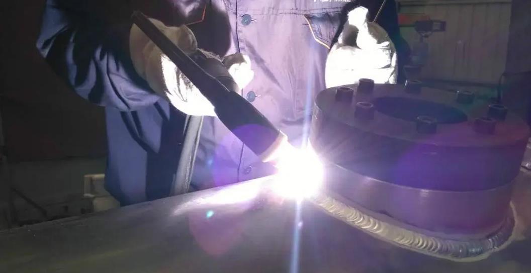
Both MIG (GMA-Gas Metal Arc Welding) and TIG are inert gas shielded welding. The difference is that TIG welding uses tungsten electrodes as fixed electrodes, while MIG welding uses the filled wire material itself as electrodes.
In the metal inert gas shielded welding process of aluminum alloy, the voltage and current act on the end of the electrode of the welding wire, and an instantaneous high pressure is generated between the electrode and the base metal, which melts the base metal and the groove, and the droplet at the end of the wire falls off and transitions vertically to the base metal. On the molten pool of the material, a weld zone is formed.
However, the application process of aluminum alloy MIG welding is relatively limited, because the softness of the aluminum wire leads to poor wire feedability, and the molten aluminum is prone to form a phenomenon of "hanging but not dripping" during welding, which is easy to cause droplets to splash. The advantage is that MIG welding is faster than TIG welding, and the welding movement range is small when welding large workpieces. By adjusting the wire feeding speed, the welding efficiency can reach several meters per minute.
laser welding
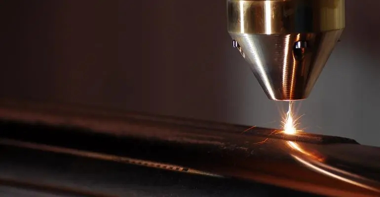
Laser beam welding (Laser Beam Welding LBW) uses high-energy laser pulses to locally heat the material in a small area. The energy of the laser radiation diffuses to the inside of the material through heat conduction, and the material is melted to form a specific molten pool. After solidification, the material is connected into One.
The advantage of laser welding is that the welding action point is small, the high-power heat source is concentrated, it is capable of welding thick plates, the heat-affected zone is narrow, and the welding deformation is small. But at the same time, laser welding has high requirements for welding positioning, expensive welding equipment, and high welding costs. For metal materials such as aluminum and magnesium, the laser reflectivity is high, and direct welding is difficult.
Irradiating materials with lasers with different power densities shows that when the power density on the workpiece reaches more than 107W/cm2, the metal in the heating zone will be gasified in a very short time, and the gas will converge into a small hole in the molten pool and form a The small hole is the center for heat transfer, and a molten pool is formed near the small hole, which is the "keyhole" effect of laser deep penetration welding. In order to avoid the unevenness of the molten pool caused by this phenomenon, it is possible to reduce the laser energy, increase the welding speed or control the remelting of the nugget area to remove the bubbles in the fusion zone and reduce the generation of pores.
Friction stir welding
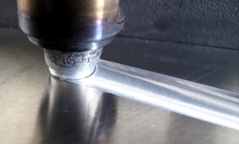
Friction Stir Welding, FSW is a new type of solid phase connection technology based on traditional friction welding technology. At the interface to be welded, when the stirring head advances along the weld seam, the temperature of the welding material rises, and the plasticized metal undergoes strong plastic deformation under the action of mechanical stirring and upsetting, and forms a dense solid-phase connection after diffusion and recrystallization.
Compared with traditional welding methods, FSW technology has the following advantages:
1. Low welding temperature and small welding deformation;
2. The mechanical properties of the weld are good;
3. The welding process is simple, economical and environmentally friendly.
Aluminum Welding Precautions
1. Before welding the aluminum alloy, the surface of the aluminum alloy should be cleaned. There should be no oil, dust, etc., and the surface of the aluminum alloy welding can be cleaned with acetone. The thick plate aluminum alloy should be cleaned with a wire brush, and then cleaned with acetone.
2. When welding aluminum alloy, the surface of the aluminum alloy should be cleaned first, and there should be no oily smoke, dust, etc. In addition, the thick aluminum alloy should be cleaned with a wire brush, and then cleaned with acetone.
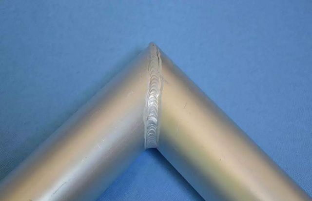
3. If the plates are compared, the plates can be preheated, which can prevent insufficient preheating from causing impenetrable welds, and fill the pits with small current arcs when extinguishing the arc.
4. Welding must be standardized and welded according to the thickness of the plate.
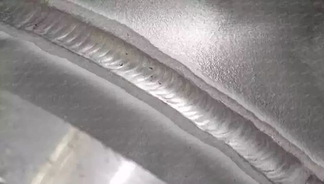
5. The cable of the welding torch should not be too long. If it is too long, the wire feeding will be stable.
Welding Case Studies
Requirements for welding materials:
Selection of shielding gas
The shielding gases used in welding include inert gases argon (Ar) and helium (He), and argon is commonly used in production. The argon used for welding aluminum and aluminum alloys must meet the following purity (volume fraction) requirements: argon is greater than 99.99%, helium is less than 0.04%, oxygen is less than 0.03%, and the mass fraction of water is less than 0.07%. At present, the purity of argon gas produced in China can generally meet this requirement, so no further purification treatment is required before use.
Selection of tungsten electrodes
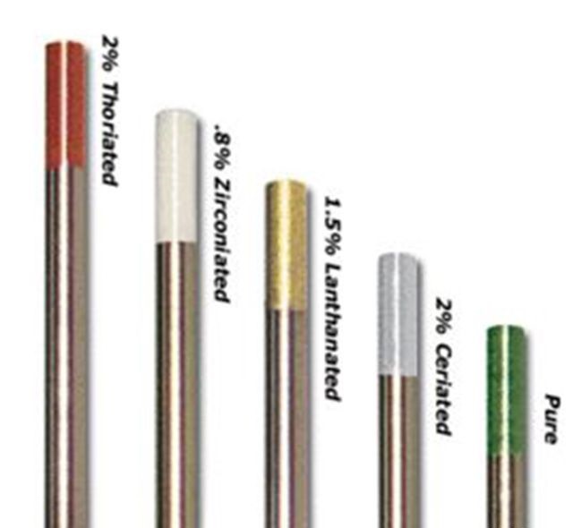
There are four types of tungsten electrode materials used in argon arc welding: pure tungsten, thoriated tungsten, cerium tungsten, and zirconium tungsten. Pure tungsten has a high melting point and boiling point, and is not easy to melt and volatilize, but its electron emission ability is worse than that of thoriated tungsten and cerium tungsten. Adding 1.0%~2.0% thorium oxide (Tho) electrode to pure tungsten is called thoriated tungsten electrode. It has strong electron emission capability, high allowable current density, and stable arc combustion. However, thorium element has certain radioactivity, which brings obstacles to its popularization and application. The currently widely used cerium tungsten electrode (brand WCe20) is made by adding 1.8%~2.2% cerium oxide (impurity ≤ 0.1%) to pure tungsten. Cerium tungsten electrode has low electronic work function, high chemical stability, high reliability of repeated arc ignition, and high allowable current density (for example, when direct current argon arc welding is used, the allowable current density is 5%~8% higher than that of thorium tungsten electrode) , low burning loss rate, and eliminates radioactivity.
Solvent selection
In the process of gas welding and carbon arc welding, the molten metal surface is easily oxidized to form an oxide film. In order to ensure the welding quality, the oxide film and other impurities must be removed with a flux. The flux used for gas welding and carbon arc welding is a mixture of chloride and fluoride powders of various potassium, sodium, lithium, calcium and other elements. When gas welding, carbon arc welding, fillet joint, lap joint and other joints are used, it is often difficult to completely remove the residual slag on the weldment. In this case, different fluxes should be selected according to different aluminum alloy materials. For aluminum-magnesium alloys, fluxes containing sodium should not be used.
Selection of welding wire
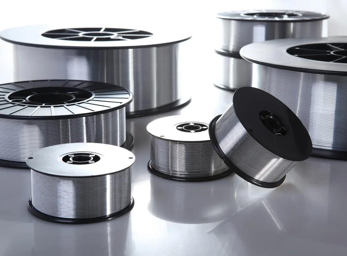
In the welding process of aluminum alloy materials, the selection of welding wire for aluminum alloys is very important, and the following should be understood before selection:
Are all aluminum alloy materials acceptable as weld filler alloys?
Can all aluminum alloys be welded?
What pitfalls should be avoided?
How to choose welding filler alloy?
What criteria should be considered in selection?
Aluminum alloy series need to know
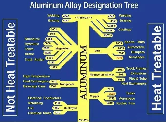
What kind of welding wire to choose?
A base metal can be welded with a variety of aluminum alloy welding materials, such as 5083-5083 welding: 5356, 5183, 5556 and other welding wires can be used. However, the welded joint obtained by each welding wire may only be the best in a certain performance. When selecting the best welding wire, the main consideration should be the end-use performance of the weldment. Overall, the following performance indicators are mainly investigated:
- Solderability and crack-free
- Tensile or shear
- Ductility of the weld
- Corrosion resistance
- High temperature performance
- Matching degree after anodizing
Requirements for welders
Should be in accordance with the "Aluminum and Aluminum Alloy Welding Construction Process Standards"
Preparation before welding
1. Mechanical methods (including shearing) should be used for aluminum groove processing. If plasma flame processing is used, no less than 3mm should be removed from the discolored part. Layers, inclusions, burrs, flash and oxide color. The surface of the groove should have a silver-white metallic luster; if necessary, perform 100% PT on the groove and the range of not less than 50 mm on both sides.
2. Surface cleaning must be carried out within the range of not less than 50 mm on the welding wire, groove surface and both sides (including removal of surface oxide film, scales, pollution and unqualified oxidation color). For grinding, you can use φ0.15~0.2 stainless steel wire disc brush, metal grinding head (that is, electric milling cutter), manual disc milling machine, file (should be a special arc file for aluminum), scraper and acetone (the white cloth dipped in acetone should be clean, do not Use cotton cloth or cotton yarn to avoid bringing out lint when wiping), but it should be noted that these tools should be cleaned before use, and care should also be taken not to press the oxide film into the base material when cleaning, so do not use too much force when cleaning However, it is not allowed to use grinding wheels or ordinary sandpaper for grinding, because the aluminum material is very soft and the sand particles will remain in the aluminum material, and defects such as pores and slag inclusions will easily occur after welding.
3. For outsourced thermal processing parts, such as heads, etc., in principle, 100% PT should be performed on the surface of the aluminum material after entering the factory, and RT should be performed on undetermined parts if necessary.
4. The surface of the welding wire can be scrubbed with a stainless steel wire brush or clean oil sandpaper; the welding wire with a thick oxide skin on the surface needs to be chemically cleaned after grinding before welding. Chemical cleaning: Soak in 70℃, 5%~10% NaOH solution for about 0.5~3min, then rinse with water, then soak in 15% HNO3 solution at room temperature for about 1~2min, rinse with warm water, and then use a hand-held Dry it with a hair dryer (air compressor is not allowed, because there is water and oil in the air) and put it in an oven at 100°C before use. This method can also be referred to for aluminum materials.
5. The cleaned welding wire and welding parts should be kept clean and dry. Do not touch or blow the welding parts with your hands. Welders generally wear white welding gloves. Do not wear dirty gloves for fear of trouble; pollution is strictly prohibited before welding, otherwise you should re- Clean up, local pollution can be partially re-cleaned; it is best to cover both sides of the bevel with white paper. Generally, welding should be done immediately after mechanical cleaning. If there is no welding within 4 hours after cleaning, it should be cleaned again before welding.
6. The assembly of the weldment should be accurate. If the assembly is not good, it should be considered to replace the parts instead of forcing the assembly to avoid excessive stress. Before formal welding, the groove size should be checked, and welding can only be performed after passing the standard.
7. The welding wire selected for tack welding and the process measures adopted are the same as the welding process.
8. Try to avoid tack welding at stress concentration places (such as weld intersections and corners on workpieces, etc.) when welding parts are assembled. The length and spacing of tack welds can be listed in the following table: (mm)
| Base metal thickness | Tack welding distance | The length of each tack weld |
|
<3 |
30-50 |
4-6 |
|
3-6 |
50-60 |
5-10 |
|
>6 |
50-80 |
10-12 |
|
Takeover or Flange |
2-4 points |
per point 3-8 |
9. Tack welds must not have defects such as cracks, pores, slag inclusions, etc., otherwise they must be removed and re-welded. Re-welding should be carried out in the nearby area instead of spot welding in the original place; when the butt weld gap is not specified in the process, it can be 2~4mm.
10. For the tack weld that will melt into the permanent weld, it is necessary to ensure penetration and remove the oxide layer on its surface (only silvery white is allowed), and make a smooth transition at both ends of the weld to facilitate arc connection, otherwise it should be trimmed.
11. When welding the longitudinal seam, the arc starting plate and the arc retreating plate must be placed at both ends of the weldment. The arc starting plate and the arc retreating plate are made of aluminum with the same grade and thickness as the welded part. Try to avoid arc craters when welding girth seams.
12. During the welding process, if the positioning solder joints are cracked, causing the edge of the board to be dislocated or the gap changes, the welding should be stopped immediately, and the welding can only be continued after repairing.
13. During the welding process, the black ash and oxides on the surface of the upper weld should be cleaned with a wire brush. Pay attention to the burner when welding, that is, the place where the arc is closed. The arc can be started 10~20mm away from the welding start, and then quickly return to the starting end for welding. The first layer is welded in a straight line.
14. Aluminum welding is deformed and prone to collapse during welding, so fixtures and backing plates should be made in a targeted manner before welding. When clamps are used, both the front and back sides of the parts need to be clamped, and the rigidity and clamping force of the clamps should be moderate, because if they are too small, they will not be able to control the deformation. The tightening force is preferably 350Kg/100mm. Soft aluminum fixtures can be made of carbon steel or stainless steel, which can slow down heat dissipation; strengthened aluminum fixtures can be made of aluminum, which can enhance heat dissipation. Longitudinal seam clamps can be of keyboard type, and ring seams can be hydraulic bulging clamps.
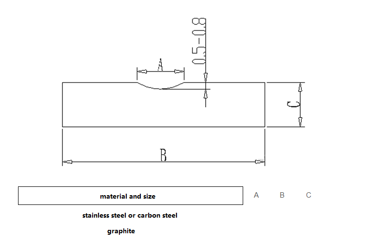
When the longitudinal seam is assembled, the gap can be appropriately increased so that there is room for shrinkage after welding; for the circular seam (including circular flanges, flanges, etc.), some reverse staggered or edged edges are reserved, because the flange will collapse and deform after welding. The material of the backing plate is generally stainless steel or carbon steel, and graphite can be used to make the backing plate for aluminum welding with low requirements. The influence on the cooling rate of the weld seam should also be considered when selecting the backing plate material.
Welding requirements
1. Licensed welders should weld according to the welding process documents and other documents.
2. When one of the following situations occurs in the welding environment, effective protective measures should be taken, otherwise welding is not allowed:
- The welding environment is not clean, with dust and smoke;
- The wind speed of the welding environment is greater than or equal to 1.5m/s;
- The relative humidity of the welding environment is greater than 80%;
- The outdoor operation is rainy or snowy; 5) The welding temperature is lower than 5°C;
3. The welding of aluminum products is located in a special site, and the site should be covered with rubber or flannelette; when welding, it should be kept away from vents, doors and windows to avoid affecting the gas protection effect.
4. Welding aluminum with manual tungsten argon arc welding generally uses AC to produce cathode atomization; melting electrode argon arc welding uses DC reverse connection. When direct current welding is used due to equipment limitations, there is generally a layer of oxide film or even black ash on the surface of the weld, which can be wiped off with a wire brush or rag. The white film formed on the surface of the weld due to flux residue or oxidation can be wiped off with a wire brush or a rag and hot water.
5. Preheating before welding: Due to the strong thermal conductivity of aluminum, when the thickness of manual argon tungsten arc welding is more than 10mm, it should be preheated before welding, but it should not exceed 100°C, and the interlayer temperature during welding should not exceed 100°C. Depending on the specific situation, it can be heated with a flame or a far-infrared ray board.
6. During the welding process, the filling point of the welding wire should not be located directly under the arc, but should be located at the edge of the molten pool, about 0.5~1.0mm away from the center line of the arc. The filling point of the welding wire should not be higher than the surface of the molten pool or in the arc.
7. A welding seam should be welded as much as possible at one time, and when rewelding after stopping welding midway, it should overlap by 10~20 mm. Before the next weld of multi-layer welds, the surface color inspection of the previous weld is carried out, only silvery white is allowed; and defects such as surface pollution and slag inclusions are thoroughly removed. The arc crater should be filled and the arc connection should be fused and penetrated.
8. Reinforcement height, height difference and width difference of type A and B joint welds are as follows mm:
|
Weld position |
Weld reinforcement |
Weld reinforcement difference |
Weld width difference |
||
|
Gas tungsten arc welding |
MIG |
Manual welding, semi-automatic welding |
Automatic welding, mechanized welding |
||
|
Flat welding |
0-3 |
0-5 |
0-2 |
0-3 |
0-2 |
|
Other weld positions |
0-4 |
0-5 |
0-3 |
0-3 |
0-2 |
9. When the thickness of the shell is less than or equal to 12mm for the D-type weld of the connecting pipe and the shell, the shell should generally be butt-welded with the edge of the edge, and the height of the edge is 25~30mm.
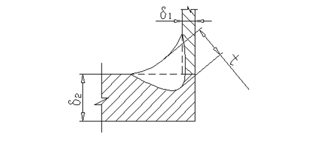
10. The weld thickness t of category C and D joints shall not be less than 0.7 times the smaller value of the thickness δ1 and δ2 of the members on both sides of the fillet weld, and shall not be less than 3mm, unless otherwise specified in the drawing. The thickness of the cover plate should not exceed 10 mm (as shown in the figure below); when the lining or the composite board is combined with a cover plate to overlap the fillet weld, the thickness of the cover plate constitutes the side length L2 of the fillet weld. The limit of side length, when L2≤4mm, should require t≥0.7 L2.
11. The welds of C and D joints should have a smooth transition with the base metal.
12. The surface of the weld and heat-affected zone should be 100% inspected, and there should be no defects such as cracks, lack of fusion, pores, arc craters, slag inclusions and spatters, and there should be no arcing points outside the weld.
13. There should be no undercut on the weld surface of aluminum pressure vessels. The undercut depth of the weld surface of the atmospheric pressure vessel shall not be greater than 0.5mm, the continuous length of the undercut shall not be greater than 100mm, and the total length of the undercut on both sides of the weld shall not exceed 10% of the length of the weld.
14. Welding sequence of heat exchange tubes of heat exchanger: tube plate assembly (the reserved length of heat exchange tubes should not be less than 4mm for later machining); tube end and tube plate cleaning; tube expansion at one end; welding tube plate on one side; Machining of unwelded heat exchange tube ends; expansion of tubes; cleaning of tube ends and tube sheets; welding of heat exchange tubes on the unwelded side.
15. Aluminum welding should pay attention to the relatively large blunt edge of the groove, generally 2~6mm. For joints with backing plates, the blunt edge may be appropriately reduced. When the aluminum plate is thin, the butt welding should consider the edge butt welding, such as when the ≤3mm considers the edge and no wire welding. Aluminum welding can be welded on both sides at the same time, with wire or no wire on the back depending on the specific situation.
Weld repair
1. For the defects that need to be repaired, the cause should be analyzed, improvement measures should be proposed, and the repair can only be started after the preparation of the welding repair process (should consider processing equipment to prevent welding deformation) (the following table shows the analysis of weld defects and their causes in general);
2. The number of rework at the same part of the weld should not exceed 2 times.
3. Generally use a metal grinding head to remove defects and bevel. If the defect is deep, it can be ground with the specified manual milling first, and then the groove surface can be ground with a metal grinding head. The groove should have a uniform width, a smooth surface and a groove that is convenient for welding. There is a certain slope at both ends of the groove (generally not greater than 1:4).
4. Defects need to be cleaned up before rework, and generally 100% PT confirmation should be carried out (if the defect is a crack, 100% PT must be carried out). When repairing welding, it is only necessary to remove the defects, do not dig too deep, if necessary, carry out RT to confirm that the defects have been completely removed. When repairing welding, do not fill the wire first, and use the arc to melt the metal in the repaired welding area.
5. The performance and quality requirements of the reworked weld should be the same as the original weld;
6. The main weld defects of aluminum welding are pores and cracks:
Causes of porosity: Aluminum welding porosity is mainly formed by hydrogen entering the welding pool. Sources of hydrogen include: materials, welding wire, shielding gas, wire feeding mechanism, welder's gloves and too high ambient humidity, such as contaminated welding wire, oxide film on the material and welding wire itself, oil stains or sweat stains on the wire feeding mechanism, etc. Precaution:
- The hydrogen content in the material and welding wire is ≤0.4mL/100g;
- Oil and oxide film should be removed from the surface of the workpiece to be welded, and the storage time should not exceed 4 hours. After surface cleaning, dry, clean and lint-free objects should be used to cover the groove and both sides;
- Use polished welding wire as far as possible, otherwise the treatment method is the same as above;
- Impurity content in protective gas: H2≤0.001%; O2≤0.02%; N2≤0.1%; H2O≤0.02%;
- Protective gas pipeline: stainless steel pipe or copper pipe is generally used, and the hose is made of plastic pipe instead of rubber or other water-absorbing hose; the cooling water pipe should be checked before welding to ensure that there is no water leakage; when the ambient humidity is high , the protective gas should be heated to purge the pipeline;
- Wire feeding mechanism: there must be no oil stains, the wire feeding tube is made of polytetrafluoroethylene tube or nylon, and the pollution and condensed water in the tube should be cleaned before welding;
- On-site environment: the temperature should not exceed 25°C, the relative humidity should not exceed 50%, and the environment should be kept clean;
- Welders: Work clothes should be white as much as possible so that pollution can be detected and cleaned up in time. When welding, pay attention to sweat and oil stains so as not to contaminate the weldment again;
- Before welding, try welding on the test plate to check whether the shielding gas and pipeline are qualified;
- Precautions in welding process: use double-sided welding instead of single-sided welding; thinner welds are more conducive to the escape of air holes than thicker ones; large-diameter welding wires are beneficial to reduce air holes; preheating before welding and slow cooling after welding ; Reduce the arc voltage, increase the current, and reduce the welding speed, which is beneficial to reduce the porosity.
Causes of cracks: The weldability of the material is poor; the crack resistance is not considered when selecting the welding wire; the structure is too restrained. Precaution:
- For aluminum materials with poor weldability, the crack resistance should be considered before welding, not just the strength; if necessary, the weldment can be welded after annealing, and then quenched and aged after welding.
- Choose welding wire with good crack resistance, such as welding wire containing low melting point elements such as Si.
- Minimize the degree of restraint of the welded joints, arrange the welding sequence reasonably, so that the weld can have a lateral shrinkage allowance to reduce the welding stress. If there is no need for tack welding, do not do tack welding, and if you can do double-sided tack welding, don't do single-sided tack welding.
- Try to change single-sided welding to double-sided welding.
Flaw detection requirements
1. 100% RT should be carried out after the seam welding of the head, and 100% RT or 100% PT should be carried out according to the regulations after forming.
2. Class A and B welds are generally 100% RT.
3. Class C and D welded joints on the container are 100% PT.
4. The repair welding seam on the aluminum surface is 100% PT.
5. 100% PT is performed on the weld marks after the temporary fixed connection welds of aluminum fixtures and tie bars are removed.
6. Other parts that require flaw detection in the drawing.
|
Try Tuofa Now! Tuofa Engineer Support Team - Real human quotes are more accurate than software quotes |
Get a free quote |
12 Welding Defects and Their Solutions in Aluminum Alloy Welding
The selection of aluminum and aluminum alloy welding wire is mainly based on the type of base metal, and the requirements for joint crack resistance, mechanical properties and corrosion resistance are comprehensively considered. Sometimes when a certain item becomes the main contradiction, the selection of welding wire should focus on solving this main contradiction, taking into account other requirements
Under normal circumstances, welding aluminum and aluminum alloys are welded with the same or similar grades of welding wire as the base metal, so that better corrosion resistance can be obtained; but when welding heat-treated aluminum alloys with a high tendency to hot cracking, the selection of welding wire is mainly from the solution Starting with crack resistance, the composition of the welding wire is very different from the base metal.
Common defects (welding problems) and preventive measures:
1. Burn through
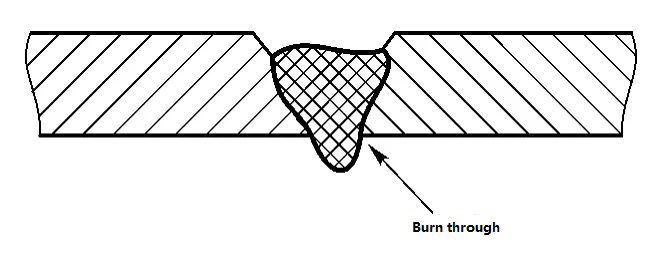
Cause:
a. Excessive heat input;
b. Improper groove processing and excessive assembly clearance of weldments;
c. The distance between the solder joints is too large during spot welding, which will cause a large amount of deformation during the welding process.
Preventive measures:
a. Appropriately reduce the welding current and arc voltage, and increase the welding speed;
b. Large blunt edge size reduces root gap;
c. Appropriately reduce the spacing of solder joints during spot welding.
2. Stomata
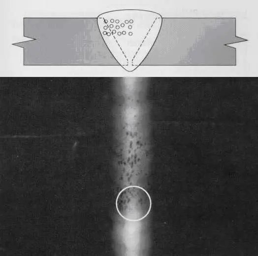
Cause:
a. There is oil, rust, dirt, dirt, etc. on the base metal or welding wire;
b. The air flow in the welding site is large, which is not conducive to gas protection;
c. The welding arc is too long, which reduces the effect of gas protection;
d. The distance between the nozzle and the workpiece is too large, and the gas protection effect is reduced;
e. Improper selection of welding parameters;
f. Air holes are generated at the place where the arc is repeated;
g. The purity of the protective gas is low, and the gas protection effect is poor;
h. The ambient air humidity is high.
Preventive measures:
a. Carefully clean the oil, dirt, rust, scale and oxide film on the surface of welding wire and weldment before welding, and use welding wire with higher deoxidizer content;
b. Reasonable selection of welding places;
c. Appropriately reduce the arc length;
d. Keep a reasonable distance between the nozzle and the weldment;
e. Try to choose a thicker welding wire and increase the thickness of the blunt edge of the workpiece groove.
f. Try not to repeat arc strikes at the same position. When repeated arc strikes are required, the arc strike point should be polished or scraped off; once a weld seam has arc strike, try to weld as long as possible, and do not break the arc at will to reduce the amount of joints. There needs to be a certain overlapping area of the weld seam at the joint;
g. Change the protective gas;
h. Check the size of the airflow;
i. Preheating base metal;
j. Check whether there is air leakage and damage to the trachea;
k. Weld when the air humidity is low, or use a heating system.
3. The arc is unstable
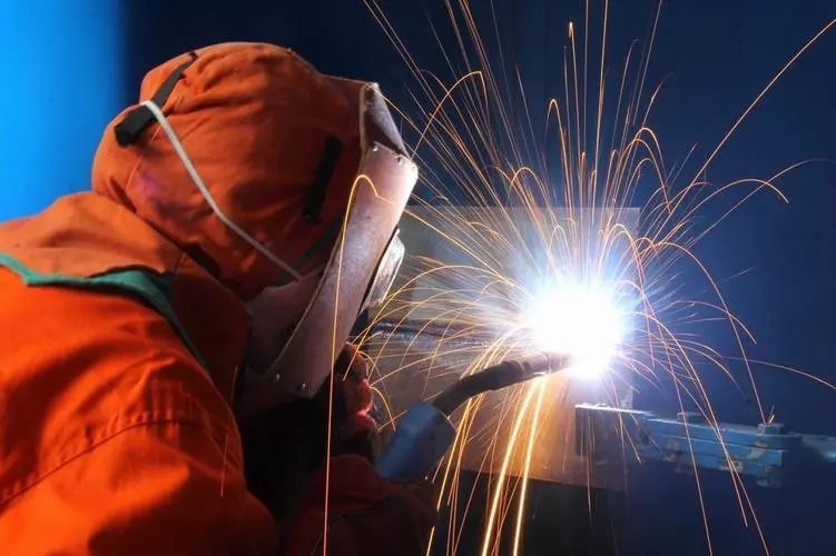
Cause:
Power cord connection, dirt, or wind.
Preventive measures:
a. Check all conductive parts and keep the surface clean;
b. Remove the dirt from the joint;
c. Try not to weld in places that can cause airflow disturbance.
4. Poor weld formation
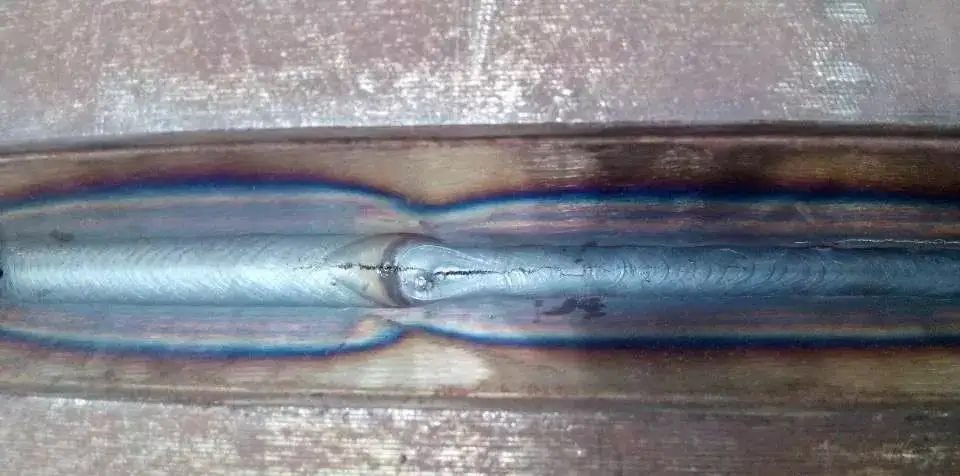
Cause:
a. Improper selection of welding specifications;
b. The angle of the welding torch is incorrect;
c. Welders are not skilled in operation;
d. The aperture of the contact tip is too large;
e. Welding wire, welding parts and shielding gas contain moisture.
Preventive measures:
a. Repeated debugging to select the appropriate welding specification;
b. Maintain an appropriate inclination angle of the welding torch;
c. Select the appropriate contact tip aperture;
d. Carefully clean the welding wire and weldment before welding to ensure the purity of the gas.
5. Incomplete penetration
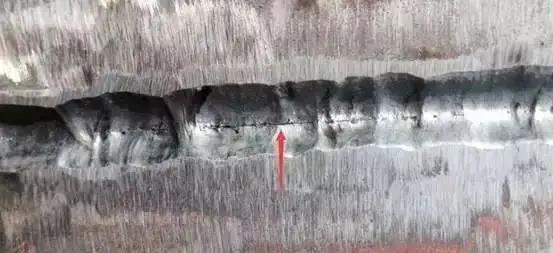
Cause:
a. The welding speed is too fast and the arc is too long;
b. Improper groove processing and too small equipment clearance;
c. The welding specification is too small;
d. The welding current is unstable.
Preventive measures:
a. Appropriately slow down the welding speed and lower the arc;
b. Appropriately reduce the blunt edge or increase the root gap;
c. Increase the welding current and arc voltage to ensure sufficient heat input energy for the base metal;
d. Add a stabilized power supply device
e. Thin welding wire helps to increase the penetration depth, and thick welding wire increases the deposition amount, so it should be selected as appropriate.
picture
6. Not fused
Cause:
a. The oxide film or rust on the welding part is not cleaned;
b. Insufficient heat input.
Preventive measures:
a. Clean the surface to be welded before welding
b. Increase the welding current and arc voltage, and reduce the welding speed;
c. U-shaped joints are used for thick plates, but V-shaped joints are generally not used.
7. Crack
Cause:
a. The structural design is unreasonable, and the welds are too concentrated, resulting in excessive restraint stress of the welded joints;
b. The molten pool is too large, overheated, and the alloying elements are burned;
c. The arc crater at the end of the weld is cooled quickly;
d. The welding wire composition does not match the base metal;
e. The depth-to-width ratio of the weld is too large.
Preventive measures:
a. Correctly design the welding structure, arrange the welds reasonably, make the welds avoid the stress concentration area as far as possible, and choose the welding sequence reasonably;
b. Reduce the welding current or increase the welding speed appropriately;
c. The arc crater operation must be correct, adding an arc strike plate or using a current attenuation device to fill up the arc crater;
d. Correct selection of welding wire.
8. Slag inclusion
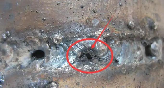
Cause:
a. Incomplete cleaning before welding;
b. Excessive welding current causes the contact tip to partially melt and mix into the molten pool to form slag inclusions;
c. The welding speed is too fast.
Preventive measures:
a. Strengthen the cleaning work before welding. During multi-pass welding, the weld seam cleaning should also be carried out after each welding pass;
b. In the case of ensuring penetration, reduce the welding current appropriately, and do not press the contact tip too low when welding with high current;
c. Properly reduce the welding speed, use welding wire with higher deoxidizer content, and increase the arc voltage.
9. Undercut
Cause:
a. The welding current is too large and the welding voltage is too high;
b. The welding speed is too fast and the filling wire is too little;
c. The torch swings unevenly.
Preventive measures:
a. Properly adjust the welding current and arc voltage;
b. Appropriately increase the wire feeding speed or reduce the welding speed;
c. Make every effort to swing the torch evenly.
10. Weld pollution
Cause:
a. Improper protective gas coverage;
b. The welding wire is not clean;
c. The base material is unclean.
Preventive measures:
a. Check whether the air supply hose is leaking, whether there is draft, whether the gas nozzle is loose, and whether the protective gas is used correctly;
b. Whether the welding materials are stored correctly;
c. Remove oil and grease before using other mechanical cleaning methods;
d. Remove the oxide before using a stainless steel brush.
11. Poor wire feeding
Cause:
A. The contact tip and the welding wire are ignited;
b. Welding wire wear;
c. Spray arc;
d. The wire feeding hose is too long or too tight;
e. The wire feed wheel is improper or worn;
f. There are many burrs, scratches, dust and dirt on the surface of welding materials.
Preventive measures:
a. Reduce the tension of the wire feed roller and use the slow start system;
b. Check the contact surface of all welding wires and minimize the metal-to-metal contact surface;
c. Check the condition of the contact tip and the wire feeding hose, and check the condition of the wire feeding wheel;
d. Check whether the diameter of the contact tip matches;
e. Use wear-resistant materials to avoid truncation during wire feeding;
f. Check the wear condition of the wire reel;
g. Select the appropriate size, shape and surface condition of the wire feed wheel;
h. Select welding materials with better surface quality.
12. Poor arc starting
Cause:
a. Poor grounding;
b. The size of the contact tip is wrong;
c. There is no protective gas.
Preventive measures:
a. Check whether all grounding conditions are good, and use slow start or hot arc starting to facilitate arc starting;
b. Check whether the inner space of the contact tip is blocked by metal materials;
c. Use the gas pre-cleaning function;
d. Change the welding parameters.
Tuofa Believes that There are Problems in Aluminum Welding
With the application of aluminum alloys in more and more industries, the problem of its repair connection has also attracted the attention of more and more scholars. Through various welding tests on aluminum alloys, it is found that the maturity of the repair technology has not yet met the development needs of the industry, and there are still various problems in it.
Gas tungsten arc welding and metal inert gas shielded welding are the two most widely used welding methods at present, but these two technologies have a wide heat-affected zone, and the weld metal needs to be melted and then solidified, which has an impact on the structure. Larger, and the residual stress is high, resulting in a serious impact on the mechanical properties of the joint. Laser welding energy beam density is high, and the depth-to-width ratio of the weld is large, but it is very easy to form pores, and its expensive cost also limits the popularization of applications. Friction stir welding provides a solution to the problem of heat, but friction stir welding requires relatively large upsetting pressure and forward driving force, and the equipment is generally complicated and bulky, which limits its development.
Conclusion
As an engineering metal material that has risen rapidly in recent years, aluminum alloy has been widely used in aerospace, automobiles, ships and other fields due to its low density, high specific strength and specific stiffness, and good corrosion resistance. .
However, a series of problems such as poor weldability and poor performance of the forming layer during welding restrict the development of aluminum alloy structural parts. Therefore, aluminum alloy welding technology has become one of the main research directions of global scholars. With its professional service and uncompromising product quality, Tuofa has won the trust of Fortune 500 companies in the welding and manufacturing of aluminum alloys.
If you're looking for a responsive, responsible and reliable manufacturer, Tuofa CNC Machining delivers on our promises through on-time and efficient delivery.
As a leading top manufacturer in Shenzhen, China, we strive to ensure that each of our customers can receive satisfactory service, because our products can speak for themselves. Our rapid prototyping, sheet metal fabrication, CNC machining services include complex and precision optical parts, automotive parts, medical devices or aerospace parts. Leave the most difficult work to Tuofa, no matter how complicated your project is, we can do our best to meet your needs.
 Tel/WeChat:
  Email:
 Home
Home
 Types of Springs: Failure Analysis and Prevention Techniques


