Knowledge of Threaded Connections, The Most Basic Professional Knowledge!
 Nov 02,2022

Because of its simple structure, convenient disassembly and assembly, threaded connections have been standardized, mass-produced, low cost, reliable connection, sufficient strength, rigidity and self-locking, and are widely used in various metal structures and mechanisms.
Tuofa CNC Machining explained in detail the case of thread processing, and by sharing our manufacturing process, let everyone know more about the fun of manufacturing.
Main parameters of thread and threaded connection
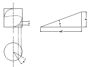
The outer surface of the thread is a cylindrical helix. A cylindrical helix is the trajectory of a point moving along the cylindrical surface, and the axial displacement a of the point is proportional to the corresponding angular displacement a. On the cylindrical surface, the continuous protrusions and grooves formed along the helix are called thread.
picture
The thread consists of an external thread and an internal thread. According to the shape of the parent body, the thread is divided into a cylindrical thread and a conical thread. According to the tooth type, it can be divided into triangular thread, rectangular thread, trapezoidal thread and serrated thread. The triangular thread is used for connection, and the latter three threads are used for transmission.
The main parameters of the thread are:
① Number of lines: If there are more than two moving points, and the same helical motion is performed on the same cylindrical surface at the same time, and the axial direction is equidistant, a multi-line helix will be formed. The number of helix lines is called the number of threads of the thread, which is represented by n.
② Rotation direction: The angular displacement direction and the axial displacement direction of the point moving along the surface of the cylinder are different. The spiral line is divided into right-handed and left-handed. The screw that is screwed clockwise is called right-handed thread, and the screw that is screwed counterclockwise is called left-handed thread. , most of the commonly used threads are right-handed.
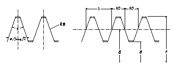
③ Tooth angle α: tooth half angle α/2: On the thread profile, the side surface connecting the tooth crest and the tooth bottom is called the tooth flank, and the angle α between the adjacent tooth flanks is called the tooth angle. The angle α/2 between the flank and the vertical line of the thread axis is called the tooth half angle.
④ Outer diameter (major diameter) d: The diameter of the imaginary cylindrical surface that coincides with the crest of the external thread or the root of the internal thread is called the outer diameter (or major diameter) of the thread, also known as the nominal diameter.
⑤ Inner diameter (minor diameter) d1: The diameter of the imaginary cylindrical surface that coincides with the root of the external thread or the crest of the internal thread is called the internal diameter (or minor diameter) of the thread.
⑥ Pitch diameter d2: It refers to the diameter of an imaginary pitch cylinder, and the generatrix of the circle passes through the place where the width of the groove and the protrusion on the tooth profile are equal.
⑦ Pitch P: the axial distance between the corresponding points on the midline of two adjacent teeth.
⑧ Lead S: the axial distance between the corresponding two points on the center line of two adjacent teeth on the same helix, S=nP, for single thread, because n=1, so S=P.
⑨ Helix angle φ: on the middle diameter cylinder, the angle between the tangent of the helix and the plane perpendicular to the thread axis.

The main threads used for connection are: ordinary thread and pipe thread. Ordinary thread profile angle is 60°, and the outer diameter d is the nominal diameter. The same nominal diameter can have threads of various pitches. The thread with the largest pitch is called coarse thread, and the rest are called fine thread. Generally, coarse thread is commonly used for connection, and it is selected according to the nominal diameter check standard. The fine thread has a small rise angle and good self-locking. The fine thread has higher strength than the coarse thread, but it is not wear-resistant and easy to slip, and is mostly used for thin-walled parts.
The pipe thread has an inch fine thread with a profile angle of 55°. The nominal diameter is the inner diameter of the pipe. There are also conical pipe threads with a profile angle of 55° and 60°. Different fillers can ensure the tightness of the connection.
Main types of threaded connections, standard connection parts
The main types of threaded connections are:
①Bolt connection: When the connected parts are not too thick, use ordinary bolts to penetrate two (or more) connected holes, and then tighten the nuts. This is the most widely used.
② Screw connection: if one of the connections is thick, screw connection can be used. The screw-in depth is related to the material of the screw and the connected parts. The minimum screw-in depth determined according to the condition of equal strength can be found in the relevant manual. This kind of connection is not suitable for the connection that is often disassembled, and the frequent disassembly can cause the wear of the screw holes, which leads to the difficulty of repair and the scrapping of the connected parts.
③ Double-ended stud connection: used for occasions where one of the connected parts is thick and often disassembled. When disassembling, just remove the nut and do not need to unscrew the stud.
When designing, pay attention to the fact that the studs must be tightened. When loosening the nut, make sure that the stud does not turn in the threaded hole. The commonly used fastening methods for double-ended stud connections are shown in the figure below:
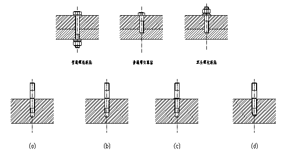
(a) Using the interference fit thread, screw it into the threaded hole to form a horizontal tightening of the entire length of the screw connection;
(b) Use the end of the thread (incomplete thread) to squeeze into the threaded hole to form a local lateral tightening;
(c) Use the end face of the retaining ring to press against the threaded hole and position the stud axially;
(d) Use the top structure of the stud to press against the bottom surface of the threaded hole to form an axial fastening.
④Set screw connection: screw the nail into the threaded hole of one part, so that the end of the nail is against the surface of another part or into the corresponding pit. It is mainly used to fix the mutual position of two parts, and it is not suitable to transmit a large force or moment.
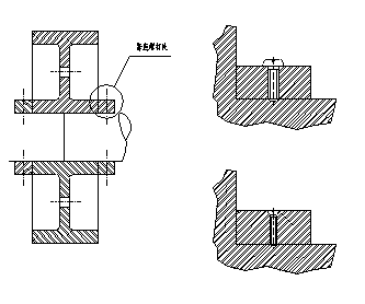
There are mainly the following six types of standard connectors for threaded connections:
① Bolts: There are two types of rough studs and refined bolts according to different machining accuracy. The commonly used bolt heads are standard hexagon head, small hexagon head, square head...
② Double-ended stud: Both ends are threaded, and the length of the thread screwed into the body end is L1. The size of L1 is related to the material of the connected parts. When steel is connected to steel, L1=d, and when steel is connected to cast iron, L1=d When L1=1.25d and L1=1.5d, when the steel is to aluminum alloy, L1=2d.
③ Screw: The structure and shape are similar to that of bolts, but there are many forms of screw heads, of which the inner and outer hexagon heads can apply a larger tightening torque. The round head and the cross head are inconvenient to apply a large torque, so the diameter should not be too large, generally not more than 10mm.
④ Set screw: There are many forms of its head and tail. The commonly used tail shapes are tapered end, flat end and cylindrical end. Generally, the tail end must have sufficient hardness.
⑤ Nut: Hexagonal nuts are commonly used, and there are also rough and refined. According to its height, it is divided into standard nut, flat nut and thick nut. If it is required to reduce weight and disassemble infrequently, flat nut can be used, and thick nut can be used in frequent disassembly.
⑥ Washer: A commonly used accessory, placed between the nut and the connected piece, can protect the support surface or prevent the nut from loosening (spring washer, etc.).
Strength level of threaded fasteners
The national standard stipulates: threaded fasteners are classified according to their material mechanical properties, and the strength level is represented by numbers: bolts are represented by two numbers, the number before the decimal point represents 1/100 of the tensile strength limit of the material, and the number after the decimal point represents the material's tensile strength limit. 10 times the ratio of yield limit to tensile strength limit. The nut is represented by a number. In order to prevent the thread pair from seizing and reducing wear, the material level of the nut should be lower than that of the bolt.
Pre-tightening and anti-loosening of threaded connections
According to whether the threaded connection is tightened or not, it is divided into loose connection and tight connection. A typical example of a loose connection is the coupling bolt that fixes the pulley, which is only acted upon by an external load.
In practical applications, most of the connections need to be tightened during assembly, and the force on the bolt at this time is called the pre-tightening force. Preload can increase joint stiffness, tightness and improve anti-loosening ability.
The standard parts of the connecting thread can meet the self-locking conditions. Friction between the nut or nail head and the support surface of the piece being coupled also helps prevent the nut from loosening. However, if the temperature changes greatly, or the nut is subjected to impact load, or vibration will gradually loosen the nut, the design must be based on working conditions, reliability requirements, and structural characteristics to consider setting up anti-loosening devices. Such anti-loosening devices can generally be divided into three categories:
① The use of friction to prevent loosening, the spring washer is a simple and easy-to-use anti-loosening part, but it is not very reliable due to uneven elasticity. Double nuts can also be used to prevent loosening. Lock nuts can also be used to prevent loosening. The upper end of the locking nut is opened and radially closed, and after tightening, it is opened, and the nut is elastically locked, which is simple and reliable, and can be disassembled and assembled many times for more important occasions.
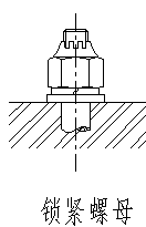
② Use the shape of the coupling to prevent loosening
Use the shape of the additional coupling, or change the shape of the threaded pair so that the threaded pair cannot rotate relative to each other. Its practices include:
Hexagon slotted nut: set a cotter pin, and drill holes at the end of the screw during installation (refer to cotter pin), which can be used for connections with large changes in impact line load.
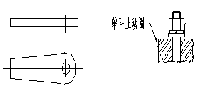
Single-ear retaining ring: one side is bent up and attached to the side of the nut, and the other side is bent and attached to the side wall of the connected piece to prevent loosening reliably.
Triple stop washer: After tightening the three nuts, pull up the two sides of the washer and stick them on the sides of the three nuts, so that the three nuts restrict each other.
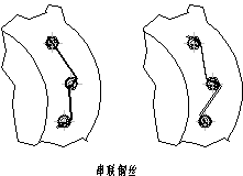
Tandem steel wire: used for connections with small number of screws and dense arrangement. Pay attention to the direction of the wire connection. The direction on the right in the picture is reasonable and has an anti-loosening effect, but it is time-consuming to install.
End punch point: It is a permanent stop and is used for threaded connections that are not intended to be disassembled.
③ Use additional materials to prevent loosening, such as welding the nut on the nail rod, welding the side to death, or coating the thread surface with adhesive, which not only prevents loosening but also seals.
Factors to be considered in bolt group structural design
① From the point of view of processing, the geometry of the joint surface should be as simple as possible, and the centroid of the bolt group is often coincident with the centroid of the joint surface. It is best to have two axes of symmetry, which are convenient for processing calculations. Strip or annular joint surfaces are usually used to reduce the amount of processing and the impact of uneven joint surfaces, while increasing the stiffness of the connection.
② For bolt groups affected by moment, the bolts should be arranged as far away as possible from the axis of symmetry, and the number of bolts on the same circle should be 4, 6, 8, 12... for ease of marking and indexing.
③ The force of the bolts should be reasonable, and the load relief device can be used for ordinary bolts subjected to lateral loads. Or use reamed hole bolts to avoid additional bending loads on the bolts (such as uneven bearing surface, incorrect nut holes, low rigidity of the connected parts, deflection of the connecting body holes, etc.).

④ Make the pre-tightening force of each bolt the same when assembling, so as to generate uniform pressure on the joint surface. Therefore, the center distance t of adjacent bolts should generally be less than 10d. For connections with tightness requirements, the t value should be designed according to relevant regulations. The size of the t value also considers the movable space of the wrench, so the t value cannot be too small.
Stress condition of bolt group
① Bolt group connection subject to lateral load: including bolt group connection, ordinary bolt connection and bolt connection for reaming holes.
For ordinary bolted connections, the compressive force is generated between the joint surfaces after the bolts are pre-tightened, and the lateral external load is resisted by friction.
The hinged hole is connected with bolts, and the bolt rod is subjected to shearing and extrusion under the action of lateral external load.
② For the bolt group connection subjected to rotational moment, the force condition is basically the same as the lateral load.
③ Bolt group connection subject to axial load: Multiple bolts are uniformly stressed and their axes are the same. It is assumed that the bolts are evenly distributed, and each bolt is subject to the same external load.
④ Bolt group subjected to turning moment: the turning trend is the same as that of M turning.
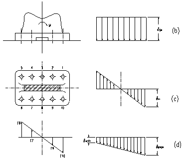
Figure (b) shows the distribution of the extrusion stress between the joint surfaces under the action of the preload.
Figure (c) shows the distribution of the extrusion stress between the joint surfaces under the action of the overturning moment.
Figure (d) is the distribution diagram of the extrusion stress after the combination of the stress generated by the overturning moment and the preload force without considering the change of the preload force of the loaded bolts. It can be seen from the figure that the extrusion stress of the left edge of the joint surface is the smallest, and the extrusion stress of the right edge is the largest.
When designing a bolted connection, no matter what kind of external load it is subjected to, the total resultant force of the bolt group is obtained first, and then the strength of a single bolt is calculated.
7. Measures to improve bolt connection strength
①Improve the uneven load distribution between threads
From the analysis of stiffness deformation, in the process of force transmission, the bolt is pulled and the pitch increases, while the nut is compressed and the pitch decreases. The research results show that the deformation of the first ring thread is the largest from the bearing surface of the nut, followed by the second ring, and then decreases gradually. Therefore, using a nut with too many turns cannot improve the connection strength. In order to improve the unfavorable situation of the load distribution on the thread, the methods often used are:
Set the suspension nut, so that both the mother body and the bolt are pulled, reducing the difference in pitch variation, and making the load distribution on the thread evenly distributed.
Use an internal oblique nut, and the screwed end of the nut is made into an internal oblique angle of 10°~15°. The stress point of the lower circles of thread teeth with the original force is moved outward, the rigidity is reduced, and the load is moved upward to make the load distribution. tend to be uniform.
Ring groove nut, the nut cuts the groove, causing the nut part to be pulled, and the effect is the same as that of the suspension nut.
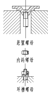
These measures are complicated to process and are only suitable for important occasions.
②Reduce bolt stress amplitude
For bolted connections subject to alternating loads, increasing the length of the bolt, reducing the cross-sectional area of the screw, or reducing the elastic cross-section E of the screw material can reduce the stiffness of the screw, such as the use of flexible bolts.
③ To reduce stress concentration, there are stress concentrations on the thread teeth of the bolt, at the end of the thread, at the transition fillet, and at the change of the rod section. Among them, the stress concentration of the thread root has a great influence, and the fillet radius of the root can be increased. For example, if r=0.1443p is increased to r=0.21p, the bolt connection strength can be increased by 24% to 40%. In addition, enlarging the transition fillet of the nail head and shank, cutting the unloading groove, using the unloading transition, and the thread end-retraction groove can reduce the concentrated stress.
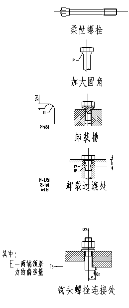
The disadvantage of these measures is the increased cost and is only used for important connections.
④ Avoid additional stress
If the supporting surface is not flat, the nut hole is not correct, the connected parts are not punched in a straight line, the rigidity of the connected parts is too small, and the hook head connection will cause additional stress to the connection, which should be avoided in the design.
⑤ Adopt a reasonable manufacturing process
The manufacturing process has a great influence on the fatigue strength of the bolt, and the residual stress generated in the thread surface layer during processing should be eliminated.
Rolled threads are better than turning threads. It is unreasonable to remove the metal fibers by turning the thread with the better surface quality, while the rolling thread uses the plastic forming of the material. After rolling, the metal structure is tight. The fiber direction is the same, and its strength is 40%~95% higher than that of turning threads.
Nitriding, cyanidation and other surface hardening treatments on the thread surface can also improve the fatigue strength of the bolt.
 Tel/WeChat:
  Email:
 Home
Home
 High-precision Thin-walled Arc Groove Track Turning Method


