High-precision Thin-walled Arc Groove Track Turning Method
 Nov 04,2022

Aiming at the process characteristics and CNC turning difficulties of thin-walled rotary metal parts, as well as the problems of low efficiency and qualified rate of using general processing fixtures, a special combined fixture is designed, which can increase the force uniformity of the clamped parts. , In the CNC machining project, reasonable turning parameters are adopted to ensure the machining accuracy of the part profile, and the problems of poor rigidity of thin-walled rotary metal parts and deformation during processing are solved.
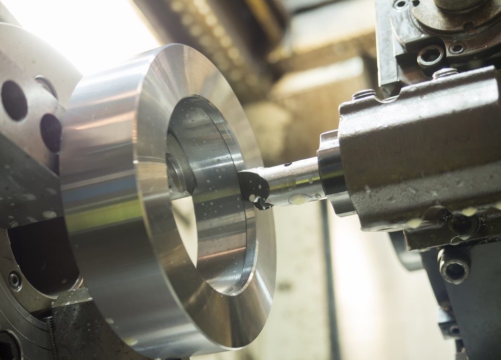
Superior CNC turning methods increase efficiency
Thin-walled revolving metal parts have the characteristics of light weight, material saving and compact structure, and are widely used in the aerospace field [1]. Thin-walled rotary metal parts are easily deformed due to poor rigidity and low strength of the parts during turning. Due to the unreasonable selection of tools and the wrong clamping of the fixture, the geometric error increases and deformation occurs during the machining process, and it is not easy to ensure the machining quality of the parts
Product process analysis
1 Part structure
The metal parts of the revolving body of the anti-nozzle (see Figure 1), the product material is 30CrMnSiA, and the quenched and tempered hardness is 42-46HRC. The maximum diameter of the product is 153mm, the shape is conical, the inner cavity is a cylindrical structure with draft, the middle position is the picture mm arc raceway, and the φ147mm outer circle forms a 4mm thin wall. In the process of CNC turning, it is not only required to ensure the machining accuracy of the arc raceway, but also to control the deformation to ensure the coaxiality of the inner hole and the outer circle relative to the center after machining.
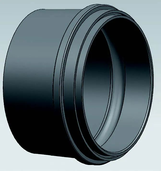
Figure 1 Metal parts of the revolving body of the anti-nozzle
2 Difficulties in processing technology
The wall thickness of the part is less than 1/13 of its aperture, and the processing rigidity is poor. The key dimension is the arc raceway, which requires a small dimensional tolerance range. The material is quenched and tempered high-hardness steel with high hardness. The thin-walled workpiece itself has poor rigidity, it is difficult to clamp when CNC turning, and it is easy to deform, and the influencing factors include clamping force, cutting force, cutting heat and elastic recovery.
Therefore, turning thin-walled parts must first solve the problems of clamping and cutting. Secondly, it is necessary to solve the problem of reasonable selection of toolholders, inserts and cutting parameters in the processing process, and finally to solve the problem of detection of ball ballistic grooves. The effective release of cutting heat and internal stress between processes during the processing can ensure the processing quality of the parts, and the ball ballistic groove can be measured indirectly.
3 Analysis of clamping deformation of universal chuck
The most commonly used fixture for clamping rotary parts for turning is the self-centering chuck. This chuck generally does not need to be aligned when clamping the workpiece, and the clamping speed is fast, but when clamping thin-walled parts, a common three-jaw clamp is used. The holding force surface is too small, which belongs to point contact, and the clamping force is not uniform, resulting in that after the part is removed, the inner and outer diameter cylindricity cannot meet the process requirements. as shown in picture 2.
Figure 2a shows the part before finishing after rough machining with three claws. Since the main force point is located in the contact part between the claw and the clamping surface of the product, the clamping deformation of the product occurs. Figure 2b shows that after machining the inner hole of the three-jaw clamping part, due to the deformation of the clamping, the measurement results show that the roundness of the inner hole is qualified, but the wall thickness is uneven. Figure 2c shows the part after processing and unloading. In the natural state, after the clamping force disappears, the outer circle of the part returns to a circle, but the inner hole becomes a prism, and the processed product is unqualified.

Figure 2 Universal fixture clamping
a) Schematic of roughing and clamping b) Schematic of finishing after turning c) Schematic of products under inspection
4 Roughing and finishing are carried out separately
The roughing and finishing of the parts are carried out separately, and the roughing removes as much as possible the allowance, the cutting force and cutting heat generated are large, the temperature rises quickly when the workpiece is turned, and the deformation is large. A certain cooling time is supplemented between roughing and finishing to eliminate cutting heat and internal stress after machining.
Processing technology scheme
Refine the selection of tools and inserts, and optimize cutting parameters to reduce cutting stress and cutting heat. Combined with the above processing factors affecting thin-walled parts, the following process steps are taken when processing the reverse nozzle. The structure and size of the reverse nozzle are shown in Figure 3.
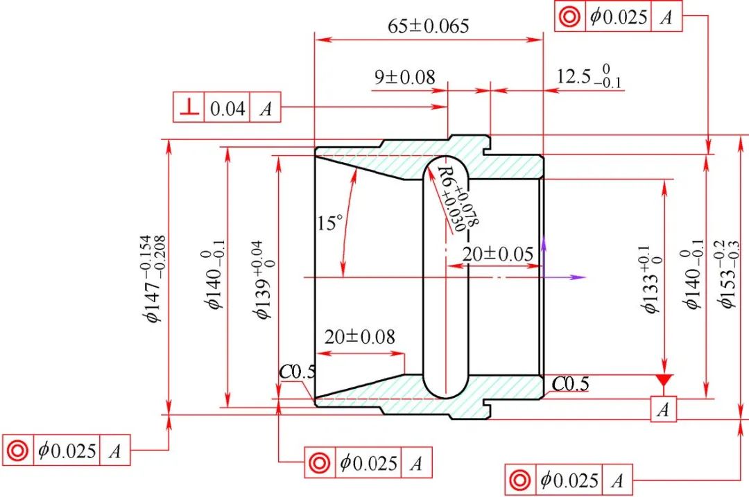
Figure 3 Structure and size of the reverse nozzle
1 Processing procedure
1) Incoming material: φ160mm×φ125mm×72mm ring, the material is 30CrMnSiA forging.
2) Rough turning: use a universal self-centering chuck to hold the outer circle of the left end of the part, and turn the outer circle of the right end. The finished product size is mm in the picture, and it is first processed to φ(157±0.2) mm; the size of the outer circle of the step is in the picture mm, First process to φ(144±0.2) mm; the finished inner hole size is the picture mm, first turn to φ(129 ± 0.2) mm; the finished raceway diameter is the picture mm, first turn to φ(136 ± 0.2) mm; The depth of the finished product is (20 ± 0.05) mm, and it is first turned to (22 ± 0.05) mm; the length of the step is guaranteed to be mm, and the chamfer is 0.5 mm × 45 °.
A universal self-centering chuck is used to clamp the outer circle of the right end of the part, and the left end is turned. The finished outer circle size is mm in the picture, first turned to φ(151±0.2) mm; 144±0.2) mm; total part length (65±0.065) mm, first turned to (69±0.2) mm; step length (9±0.08) mm, first turned to (13±0.1) mm; bevel length finished size (20±0.08), first turn to (22±0.2) mm; CNC turning inner hole angle 15°±10′, chamfering 0.5mm×45°.
3) Quenching and tempering heat treatment: Quenching and tempering hardness 42~46HRC.
4) Semi-finishing: After heat treatment, the parts are semi-finished, and the outer circle at the left end of the part is clamped by a fan-shaped soft claw, and the right end is processed, leaving a 0.5mm finishing allowance on one side, and turning the outer circle to mm in the picture; Picture mm; inner hole to picture mm; raceway to picture mm; part depth to (20.5±0.05) mm; ensure step length size picture mm, chamfer 0.5mm × 45°.
Use the inner support claw to support the inner hole of the right end, process the left end, leave 0.5mm finishing allowance on one side, turn the outer circle to the picture mm; the outer circle of the step to the picture mm; the total length of the part to (66±0.065) mm; the step length To (10±0.08) mm; bevel length to (20.5±0.08) mm; inner hole angle 15°±10′; chamfering 0.5mm×45°. Remove the part and let it sit for a period of time to fully release the stress.
5) Fine turning: Process the inner hole of the fan-shaped soft claw to the mm shown in the picture, and clamp the outer circle of the left end of the part. The clamping force should not be too large. Use a torque wrench to control it at (10±1) N m, and control the cutting depth of each tool. In 0.15 ~ 0.2mm. Turn the outer circle and inner hole of the right end to ensure that the outer circle size picture mm and picture mm in the design drawing are in mm; the inner hole size picture is mm; the inner hole angle is 15°±8′; the ball ballistic diameter picture is mm; the raceway arc picture is mm; Turning raceway width (20±0.05) mm; guaranteed step size in mm; chamfering 0.5mm×45°.
Use the fan-shaped soft claw to support the inner hole of the right end of the part, and turn the outer circle and inner hole of the left end to ensure that the outer circle size is mm, the outer circle size of the step is mm, the length dimension is (65±0.065) mm, and the step length (9±0.08 ) mm, the inner hole angle is 15°±10′, the bevel length is (20±0.08) mm, and the chamfering angle is 0.5mm×45°.
2 Improvement of workpiece fixture.
Make an inclusive soft claw to reduce the clamping deformation of the part. The end teeth at the bottom of the soft claw are positioned on the chuck to maintain a high repeat installation accuracy. The sector-shaped soft claw is welded on the chuck and boring to a diameter slightly larger than the outer diameter of the part. The inner hole is generally 0.02-0.04mm larger than the outer diameter of the part, which maximizes the clamping area and distributes the clamping force evenly on the part, which can effectively reduce the deformation of the part and ensure that the jaws are tightly combined with the workpiece. To ensure the stability of the clamping. As shown in Figure 4.
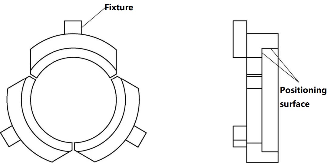
Figure 4 Schematic diagram of the fixture for machining inner holes
Put the reverse nozzle after semi-finish CNC turning into the processed soft claw, and process the right end step and inner hole. Then make a pair of circular braces (see Figure 5), and use the mm inner hole of the size picture on the right side of Figure 3 as the clamping surface to process the inner and outer taper surfaces at the left end.
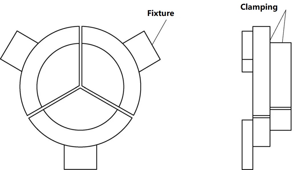
Figure 5 Schematic diagram of circular support
3 Choose the right tool
During the cutting process, the performance of the tool material has a great relationship with the cutting efficiency and the quality of the machined surface. Therefore, choosing a reasonable tool can ensure the quality and production efficiency of the product. Table 1 shows the machining tools that the author explored during the machining process. Compared with the previously selected tools, it can better reduce the generation of cutting force and effectively control the deformation of parts.
Table 1 Machining tools and grades
| Tool name | Tool holder grade | Name | Information |
| Cylindrical knife (roughing) | DCLNR2525M12-M | CNMG120404-ML,TT5080 | The 80° outer round blade, can withstand large cutting force, the blade material is TT5080 |
| Cylindrical knife (semi-finishing) | DCLNR2525M12-M | CNMG120404-MF1,CP500 | The 80° outer round blade, high temperature resistance, large front Angle, can reduce the cutting deformation, the blade material is CP500 |
| Cylindrical knife (finishing) | DDJNR2525M15 | DNMG150604-MF1,CP200 | The 55° diamond blade, with a large side deviation Angle, can effectively reduce the radial cutting force, reduce the deformation of the workpiece, the blade material is CP200 |
| Inner hole cutter (roughing) | A32-DCLNR12 | CNMG120404-ML,TT5080 | The 80° outer round blade, which can withstand a large cutting force, can quickly and efficiently remove the margin, and the blade material is TT5080 |
| Inner hole cutter (semi-finishing) | A32-DCLNR12 | CNMG120404-MF1,CP500 | The 80° outer round blade, high temperature resistance, large front Angle, can reduce the cutting deformation, the blade material is CP500 |
| Inner hole cutter (finishing) | S32-SDUCR11 | DCMT11T30LF,KC5010 | The 55° diamond-shaped inner hole turning insert with a diameter of 32mm can reduce the deformation and can process the taper of the left end at one time |
| R2 arc knife | MGNVR3732-4 | N123H2-0400-RM,4325 | R2mm arc blade |
| Face grooving knife | NER2020K2 K5KV03 | NG2M200LK,KC730 | 2mm wide end cutting knife, large front corner, sharp edge, can effectively reduce the cutting force |
4 Choose reasonable cutting parameters
According to the part material, size requirements and surface roughness requirements, determine the cutting parameters, see Table 2.
Table 2 Cutting parameters
picture
Inspection and Measurement
1 Measurement method of raceway diameter
The diameter of the design raceway is the picture mm, and the ordinary vernier caliper cannot be measured directly due to structural limitations, so a special inspection tool needs to be made, and the comparison method is used for measurement. The specific method is: remove the dial indicator end nut with a minimum measurement accuracy of 0.01mm and a range of 10mm, make a self-made extension rod with a diameter of 8mm and a length of 25mm, and rely on an M2.5 socket head cap screw. Fix it, connect it to the dial indicator, process the other end of the extension rod into an arc with a radius of 4mm, make the length of the screw connected to the dial indicator > 140mm, and adjust the outer diameter micrometer with a range of 125-150mm to 139mm, Calibrate the dial gauge.
When using the dial indicator to measure the diameter of the raceway, the dial faces the operator, and the maximum value of the arc top is measured. The difference between the maximum value measured by the dial indicator and the calibration value is the machining allowance. The self-made raceway diameter measuring tool (see Figure 6) can accurately measure the actual processed raceway diameter value, thereby providing data for the design process document.
| Lathe tool name | Spindle speed/(r/min) | Feed/(mm/r)0.2 | Cutting depth/mm |
| Cylindrical rough turning tool | 230 | 0.2 | 1.5 |
| Cylindrical semi-finishing turning tool | 300 | 0.15 | 0.4 |
| Cylindrical turning tool | 320 | 0.15 | 0.2 |
| Rough turning tool for inner hole | 300 | 0.2 | 1.5 |
| Inner hole semi-finishing turning tool | 320 | 0.15 | 0.3 |
| Inner hole finishing tool | 350 | 0.15 | 0.2 |
| R6mm grooving knife (semi-finishing) | 180 | 0.12 | 0.3 |
| R6mm grooving knife (fine turning) | 200 | 0.1 | 0.15 |
| face grooving knife | 200 | 0.06 | 2 |
Figure 6 Self-made measuring tool for raceway diameter
2 Measuring method of raceway arc radius
The radius of the raceway arc is mm in the picture. The steel ball with φ12.0mm is placed at the bottom of the raceway groove for measurement, and the feeler gauge is used to detect it. When , it is judged that the arc radius of the raceway is qualified and meets the design requirements.
Tuofa CNC Machining Insights - tuofa-cncmachining.com
By analyzing the process characteristics of thin-walled rotary metal parts and the key elements that affect the machining quality, Tuofa CNC machining expounds the defects of the general fixture for CNC turning machining, and adopts the optimized clamping scheme, tools and CNC turning parameters to provide a set of Turning solutions for thin-walled metal parts of revolution. Practice has shown that this process scheme is suitable for the processing of such thin-walled parts, and this scheme improves the processing qualification rate of the parts from 55% to 99.7%.
 Tel/WeChat:
  Email:
 Home
Home
 What are the Methods for Deburring Parts?


