Innovation of Machining Method for Flat Deep Groove Parts
 Nov 08,2022

The operation method specifically relates to a turning machining method for the main valve of a plane deep groove part. Tuofa CNC machining designed the special grooving tool for deep groove machining on the plane. Through the design innovation of the tool structure and shape and the rational arrangement of the process, the machining of the plane deep groove parts has been completed.
Background Art: The machining method is applied to the field of batch turning machining and manufacturing of flat and deep grooved parts.
1. Parts structure and technical requirements
The structure of the part is shown in Figure 1-7. The material of the part is 2Cr13, which needs to be quenched and tempered after rough turning. The hardness is 269~292HB. The tolerance of the inner hole size of the part is φ42mm. ° The surface roughness value of the cone surface is Ra=0.4μm, and the surface roughness value of the outer circle 120° cone surface is Ra=0.4μm. The technical requirements stipulate that the local heat treatment hardness of the cone surface is 48~52HRC, and it is matched with the relevant parts.
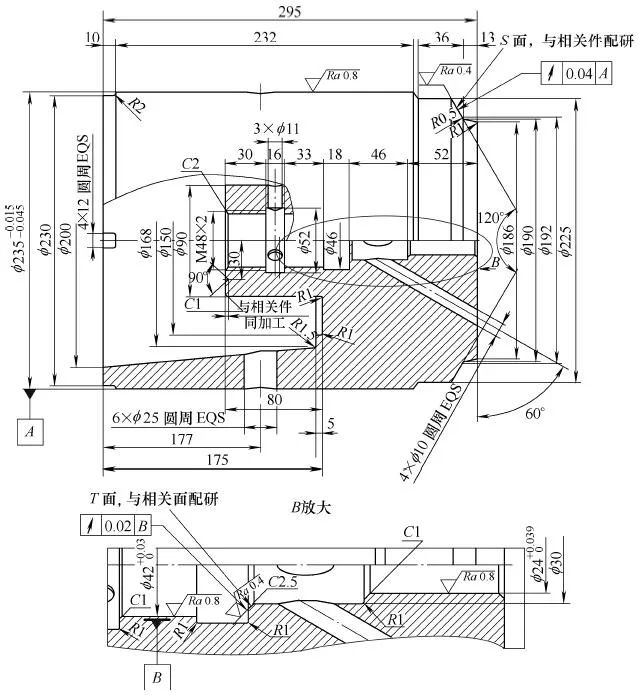
Figure 1-7 Main valve of a part
2. Processing technology analysis
The machining of this part has the following technical difficulties:
(1) The end face of the plane groove is 175mm deep from the left end face of the part, and 80mm from the end face with a size of φ90mm. The space at the deep groove is small, the cutting amount is large, and chip removal is difficult.
(2) The cutting performance of stainless steel is poor, mainly in: ① High plasticity, which makes the work hardening serious during the processing and increases the cutting resistance. ②The high cutting temperature makes the tool easy to wear. ③It is easy to stick the knife and generate built-up edge. ④ The chips are not easy to curl and break.
3. Technical measures
In view of the above processing difficulties, the following technical measures have been taken:
(1) Design and manufacture a special grooving tool for turning plane deep groove machining. When CNC turning a plane groove, one of the tool tips of the grooving tool is equivalent to a turning hole. In order to avoid the interference between the CNC turning tool and the arc surface of the workpiece, the rear of the tool at the tool tip is made into an arc according to the diameter of the plane groove arc. shape, and ensure a certain back angle. The other tool tip of the plane grooving tool is equivalent to turning the outer circle. When turning the plane deep groove, the tool tip is very long, the rigidity is poor, and it is easy to cause vibration. It is also made into an arc surface, and it is guaranteed to have a certain back angle.
The grooving knife is composed of three welding parts: the clamping part, the arc surface cutter body, and the carbide cutter head:
①The clamping part is made of 45 steel.
②Double arc surface cutter body is made of 30CrMnSi steel pipe with outer diameter φ140mm and inner hole φ128mm processed into strips by horizontal milling. In order to increase the strength of the cutter body, the heat treatment quenching hardness is 38~42HRC.
③The cemented carbide cutter head adopts YG8N, YW1, YW2, and the blade type is C304.
Grooving knife geometric parameters and cutting characteristics:
①The band-shaped chips have a strong performance of drilling when they see the seam. The method of grooving improves the chip removal conditions, prolongs the service life of the tool by 3 times, and increases the production efficiency by 1 time.
②The large rake angle is matched with negative chamfering, and the tool tip adopts R1mm rounded corner, which reduces the cutting force, strengthens the cutting edge, and increases the tool life. The structure of the grooving tool is shown in Figure 1-8.
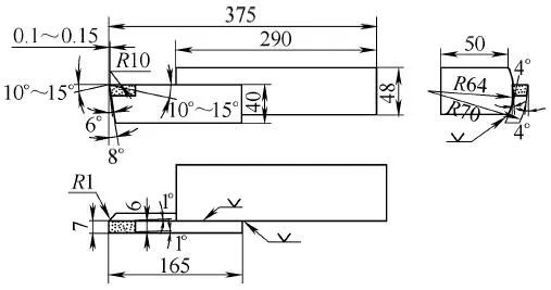
Figure 1-8 Special grooving knife
(2) Design and manufacture a round clamping inner hole tool holder to solve the processing problems of turning M48×2 inner thread, φ42 picture mm and φ30mm inner hole, and inner hole empty tool. The structure is shown in Figure 1-9.
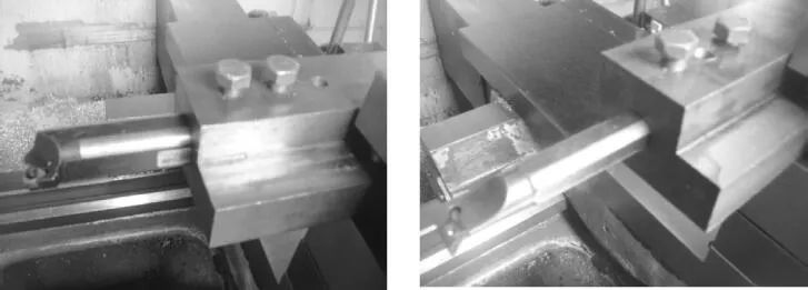
Figure 1-9 Circular clamping inner hole tool holder
(3) Design and manufacture the tool table inner hole tool holder, which solves the taper processing problem of the large end diameter of φ200mm and the small end diameter of φ168mm. The structure is shown in Figure 1-10.
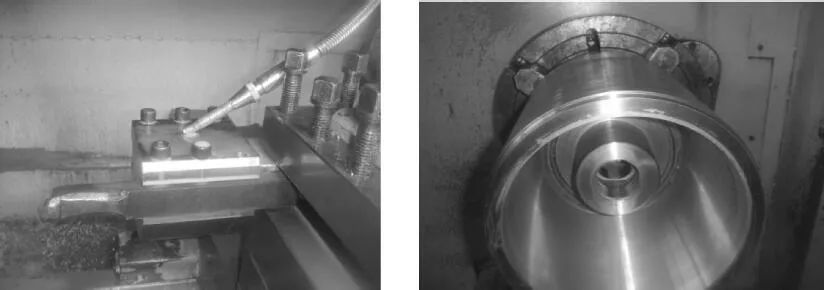
Figure 1-10 Knife table inner hole tool holder
4. CNC turning process plan
The process plan adopted by CNC machining is:
①Rough turning, the outer diameter of the rough turning is φ239mm, the control length is 298mm, and the inner hole diameter is φ143mm and the depth is 90mm.
② Quenching and tempering, 280~320HBW.
③Semi-finished turning, inner hole φ42mm, φ24mm, T surface with Ra=0.4μm allowance 0.4~0.5mm, outer circle φ235mm, Ra=0.4μm S surface with allowance 0.6~0.7mm , The diameter of the big end is φ200mm, and the taper of the diameter of the small end is φ168mm, and the CNC finishing volume is 2~3mm.
④CNC turning, control the taper of big end diameter φ200mm and small end diameter φ168mm.
⑤ Draw a line.
⑥Vertical milling, 4×12 circular distribution.
⑦ Pliers, 6×φ25mm are evenly distributed around the circumference, 3×φ11mm, 4×φ10mm are evenly distributed around the circumference.
⑧Surface quenching, hardness 45~48HRC (at the inner hole with tolerance, the conical surface T surface of Ra=0.4μm, the conical surface S surface of outer circle Ra=0.4μm).
⑨ External grinding, φ235 mm in picture.
⑩ Internal grinding, φ42 picture mm, φ24 picture mm, to ensure position tolerance.
⑪ The CNC turning single-action chuck is aligned to ensure the position tolerance of the workpiece. The conical T surface of the inner hole Ra=0.4μm is machined (YT726 inner hole welding tool), and the cubic boron nitride tool is used to turn the outer circle Ra=0.4μm. Taper surface S surface, and use diamond abrasive paste to polish Ra=0.4μm.
 Tel/WeChat:
  Email:
 Home
Home
 The Best Process for High-Precision Thin-walled Aluminum Cylinder Parts


