The Best Process for High-Precision Thin-walled Aluminum Cylinder Parts
 Nov 08,2022

The operation method specifically relates to a numerical control machining method of aluminum cylinder parts, especially a processing method of precision thin-walled aluminum cylinder parts.
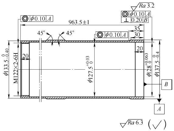
Figure 1-11 Thin-walled aluminum cylinder parts
In custom CNC machining services, CNC technology scheme for aluminum cylinder parts: At present, ordinary lathes or CNC machine tools are generally used for the processing of precision thin-walled aluminum cylinder parts, and general-purpose fixtures and special fixtures are used for radial clamping. Under the combined action of force and cutting heat, it is very easy to deform, and it cannot meet the requirements of the size and shape accuracy of the parts.
This operation method provides a processing method for aluminum cylinder parts, which solves the problem of deformation during the processing of precision thin-walled aluminum cylinder parts.
Blanking or forming aluminum tube parts blanks
The aluminum tube parts are processed by tube material. If the structure of the parts is not suitable for processing with pipe materials, in order to avoid material waste, casting blanks can be used for parts that do not need to withstand high overload and have no special requirements for comprehensive mechanical properties; if the parts need to withstand a certain high overload, there are corresponding requirements for comprehensive mechanical properties , under the premise of saving costs, die forging can be considered to form the blank, but the corresponding blank production technical requirements must be put forward according to the product design requirements.
The outer diameter of the rough-turned aluminum tube parts and the full length of the workpiece
First, put the standard specification aluminum tube of the aluminum tube parts into the full-length expansion tile fixture, use the front and rear top double tops, and rough the outer diameter and the full length of the workpiece on the lathe. A horizontal lathe is used for rough machining. Since the raw material is a thin-walled tube material, a full-length expansion tile fixture can be used to put it into the workpiece, as shown in Figure 1-12. The expansion tile is made of high-strength spring steel 65Mn, and the hardness after heat treatment can reach 50~55HRC.
There is a gap of 0.2~0.3mm in the inner hole of the cylinder part. The blade selected for roughing is an indexable blade TCMT160404-PR, and the tool nose arc is R0.4mm. The machining allowance for rough machining is 3~4mm in the diameter direction and 3~4mm in the end face. The cutting parameters are: cutting speed vc=180~250m/min, feed amount f=0.2~0.3mm/r, back cut ap=1.5~2mm.

Figure 1-12 Schematic diagram of the outer diameter and full-length expansion tile fixture of rough-turned aluminum cylinder parts
Rough turning the inner hole of aluminum cylinder parts
Put the tooling fixture of the inner hole fixture of the rough and fine turning aluminum barrel parts into the inner hole fixture of the rough and fine turning aluminum barrel parts, and use the inner hole fixture of the rough and fine turning aluminum barrel parts on the lathe to clamp the rough turning aluminum barrel. The way of the inner hole fixture of the part, the inner hole of the aluminum cylinder part is roughed. The inner hole fixture for rough and fine turning aluminum cylinder parts includes flange 1, positioning sleeve 2, clamping body 3, screw 4, pull pin 5, sliding core 6, positioning block 7, taper sleeve 8 and clamping shoe 9, flange plate 1.
The positioning sleeve 2 and the clamping body 3 are sequentially fixed and connected as a whole, the sliding core 6 is located in the central hole of the positioning sleeve 2, the front end of the positioning sleeve 2 is threadedly connected with the positioning block 7, and the inner hole of the front end of the clamping body 3 is fixed with a tapered sleeve 8, The clamping shoe 9 is arranged in the cone sleeve, and its rear end is fixedly connected with the sliding core 6 through the pull pin 5. The pulling pin can move back and forth in the limit hole of the positioning sleeve, and the outer cone surface of the clamping shoe 9 is connected to the cone sleeve 8. to match the inner cone (see Figure 1-13).
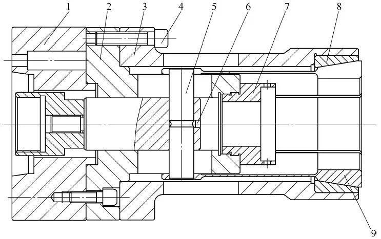
Figure 1-13 Schematic diagram of the inner hole fixture for clamping rough and fine turning aluminum cylinder parts
1—Flange 2—Locating Sleeve 3—Clamping Body 4—Screw 5—Pull Pin 6—Sliding Core 7—Locating Block 8—Taper Sleeve 9—Clamping Shoe
The inner hole process of rough turning aluminum tube parts adopts a horizontal lathe. Since the workpiece is a thin-walled tube material, the normal clamping will cause deformation of the workpiece, the size is out of tolerance, and the coaxiality cannot be guaranteed, so a rough turning aluminum tube is used. The inner hole fixture of the part, as shown in Figure 1-14, is used on the machine tool to clamp the inner hole fixture of the rough and fine turning aluminum tube parts, and the inner hole clamp of the rough turning aluminum tube parts is processed in a specific way.
The inner hole clamp of the aluminum tube parts of the rough turning is made of high-quality carbon tool steel T8A, and the hardness after quenching can reach 55HRC. The wall thickness of the inner hole clamp of the aluminum tube parts reaches 18mm, which can ensure its strength requirements. The inner hole fixture of rough turning aluminum tube parts is repeatedly processed by rough turning, quenching, finishing turning, grinding and other processes. It can ensure the accuracy after repeated clamping and disassembly, and meet the production and processing requirements. The specific implementation structure is shown in Figure 1-15.
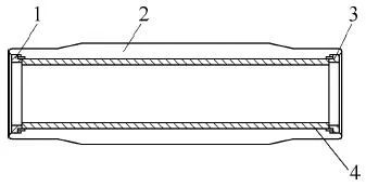
Figure 1-14 Schematic diagram of the inner hole fixture structure of rough-turned aluminum tube parts
1—Rough turning cylinder left end cover 2—Rough turning inner hole clamp body 3—Rough turning cylinder right end cover 4—Workpiece
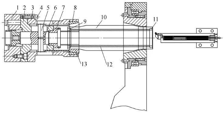
Figure 1-15 Schematic diagram of the specific implementation structure of rough and fine turning of the inner hole of aluminum cylinder parts
1—Flange 2—Locating sleeve 3—Clamping body 4—Screw 5—Pull pin 6—Sliding core 7—Locating block 8—Taper sleeve 9—Left end cover 10—Clamp body 11—Right end cover 12—Workpiece 13—Clamp watt
The clamping shoe has an outer cone surface structure, which matches the inner cone surface of the cone sleeve, and a plug to prevent the pull pin from coming out is installed on the clamping body. The front end of the clamping shoe is evenly distributed with a plurality of gaps along the circumference, which is convenient for the elastic deformation of the clamping shoe to clamp the workpiece. The spindle oil cylinder of the machine tool drives the sliding core to slide in the positioning sleeve, and the spindle oil cylinder drives the sliding core to pull the pull pin together with the inclined surface of the clamping shoe to slide mutually with the inclined surface of the tapered sleeve in the fixture body, and the workpiece is clamped radially.
The workpiece is put into the inner hole clamp of the rough-turned aluminum cylinder part, and after the two ends are axially pressed by the end caps, the whole is put into the inner hole of the inner hole clamp of the rough-turned aluminum cylinder part and clamped. The machining allowance in this process is 2~3mm in the diameter direction, and the end face of the inner hole is 1~2mm. The cutting parameters are: cutting speed vc=180~250m/min, feed amount f=0.2~0.3mm/r, back cut amount ap=1.5~2mm.
Stability treatment
The stabilization treatment is generally cold and heat cycle or cold and heat shock aging. The stability treatment process and parameters are generally as follows: firstly cool, the temperature is -100°C, and keep for 2h; air-cooled and return to room temperature, and then keep for more than 3h, and then heat aging, the temperature is 185~195°C, and the heat preservation is 2~3h; After the furnace is cooled to 80°C, it can be air-cooled. The cycle times, process positions and processing parameters of the stability treatment should be determined according to the structure and technical requirements of the parts.
Finishing shape process
Using the elastic airbag clamp for precision turning aluminum tube parts (see Figure 1-16), the workpiece is mounted on the positioning table of the clamping body and the positioning surface of the positioning retaining ring to realize the positioning of the workpiece. By inflating the air bag 4 set on the clamping body, the workpiece is tightened, and then the shape of the aluminum cylinder part is finished.
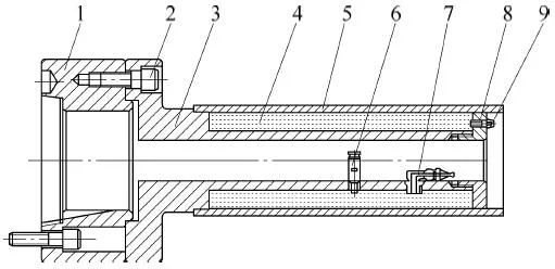
Figure 1-16 Schematic diagram of the structure of the elastic airbag fixture for the precision-turned aluminum tube parts
1—Flange 2—Screw 3—Clamping body 4—Airbag 5—Workpiece 6—Safety valve 7—Quick release valve 8—Locating stop ring 9—Quick pipe joint
After the stability treatment, the finishing process is carried out. Since this process is a finishing process, the size of the finished product is the size of the finished product, and the reference is fixed. The equipment with high precision, stable state and sufficient cooling should be used to complete the processing. Fixture design should consider improving positioning dimensional accuracy requirements. During the machining process, the machining consistency of the reference positioning dimensions of the parts should be ensured to ensure that the parts and the fixture positioning parts achieve the best fit during finishing. Therefore, the elastic airbag clamp for precision-turned aluminum cylinder parts is specially designed.
In order to solve the problem of clamping and deformation of a large number of high-precision non-ferrous metal thin-walled workpieces, this operation method provides an elastic air bag clamp for finishing aluminum cylinder parts. The specific implementation structure is shown in Figure 1-17.
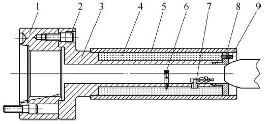
Figure 1-17 Schematic diagram of the specific implementation structure of the outer diameter and full length of the finished aluminum cylinder parts
1—Flange plate 2—Screw 3—Clamping body 4—Airbag 5—Workpiece 6—Safety valve 7—Quick release valve 8—Locating retaining ring 9—Quick change pipe joint
The clamp body 3 is fixed on the machine tool flange 1 by screws 2, the air bag 4 is sleeved on the clamp body 3, the connecting pipe joints of the air bag 4 are put into the corresponding positioning holes of the clamp body, and the positioning stop ring 8 is installed on the clamp body. Specifically, the airbag is limited in position. The safety valve 6 and the quick release valve 7 are installed in the corresponding positioning holes on the clamping body 3 and connected with the corresponding pipe joint of the airbag. The quick-change pipe joint 9 with a one-way valve is from Pass through the positioning holes of the positioning baffle ring 8 and connect with the pipe joints of the airbag 4, check each joint and conduct an air tightness test.
When the airbag is not inflated, the workpiece 5 is installed on the positioning table of the clamping body 3 and the positioning surface of the positioning stop ring 8 to realize the positioning of the thin-walled workpiece. 4. Inflate, set the air pressure of the air bag 4 through the safety valve. When the inflation pressure is greater than the set pressure of the safety valve, the safety valve starts to work and the air bag is inflated. Under the action of the elastic force of the air bag, the workpiece is tightened to achieve The workpiece 5 is clamped to start processing. Detect the workpiece 5, adjust the pressure of the air bag, pull the handle of the quick release valve 7 after the workpiece is processed, and deflate the air bag 4. After the design requirements are met, remove the workpiece 5 and the processing is completed.
The inflatable air bag itself is elastic, and the air bag tightening force acts evenly on the thin-walled aluminum tube parts. The size of the elastic force of the airbag can be set by the safety valve, and the size of the airbag tensioning force can be adjusted according to the wall thickness and strength of the thin-walled aluminum tube parts. The fixture device is convenient for loading and unloading workpieces, and can ensure the processing accuracy requirements of precision thin-walled aluminum cylinder parts. The machining allowance is 0.5~1mm in the diameter direction, and the machining allowance for the outer diameter end face is 0.2~0.5mm. The cutting parameters are: cutting speed vc=300~380m/min, feed amount f=0.05~0.1mm/r, back cut amount ap=0.05~0.15mm.
|
Try Tuofa Now! Tuofa Engineer Support Team - Real human quotes are more accurate than software quotes |
Get a free quote |
Finishing the inner hole process
The workpiece is loaded into the inner hole fixture of the finishing aluminum cylinder parts by means of datum outer circle positioning and axial thread pressing, and then clamped by the clamping shoe 9 (see Figure 1-13) of the inner hole fixture of the rough and fine turning aluminum cylinder parts. Tighten one end of the inner hole jig for the aluminum barrel parts of the fine turning, and the other end uses the ferrule 3 of the integral center frame (see Figure 1-18) to abut the body 2 of the inner hole jig of the fine turning aluminum barrel parts (see Figure 1-19) on the outer cone to complete the clamping. The vibration reduction tool is called to process the inner hole of the aluminum cylinder part, and the machining allowance is 0.5~1mm in the diameter direction. The cutting parameters are: cutting speed vc=300~380m/min, feed rate f=0.05~0.1mm /r, the amount of back-feeding knife ap=0.05~0.15mm.
Since this process is a finishing process, CNC machine tools or turning center equipment with high precision, stable state and sufficient cooling should be used to complete the finishing. Before each shift starts to process parts, it is necessary to preheat the equipment, make the equipment idle for more than 0.5h, and then start processing after reaching the best stable state of the equipment. According to the precision requirements of parts processing, the radial runout and axial play of the main shaft of the equipment should be checked before processing to meet the processing requirements.
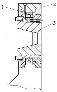
Figure 1-18 Schematic diagram of the structure of the integral center frame supporting the inner hole fixture of the rough and fine turning aluminum parts
1-Bearing 2-Base 3-Ring
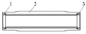
Figure 1-19 Schematic diagram of the inner hole fixture structure of fine-turned aluminum simple parts
1-Left end cover 2-Main body 3-Right end cover
Tooling design guarantee tolerance requirements
Design special tooling for inner hole fixture of precision turning aluminum tube parts to ensure processing quality. The tooling design should consider reliable positioning, and the clamping method should avoid force deformation of the parts, and adopt the method of datum outer circle positioning and axial thread compression. The positioning part of the fixture and the reference outer circle of the part are clearance fit, and the size of the clearance should meet the position tolerance requirements.
During the machining process, the clamping of the workpiece should ensure that the positioning of the workpiece and the fixture, the flatness and parallelism of the pressing surface are in good condition, and each surface should be cleaned to ensure that no chips are trapped. The positioning of each component of the fixture should ensure the geometric tolerance of the workpiece. The pressing state is appropriately adjusted according to the size of the cutting force, and the workpiece clamping cannot be too tight to avoid the deformation of the clamping force after processing.
Importance of fixtures
The clamping shoe 13 (see Figure 1-15) of the inner hole fixture for rough and finishing aluminum barrel parts clamps one end of the inner hole fixture for finishing aluminum barrel parts, and the other end uses an integral type that supports the inner hole fixture for rough and finishing aluminum barrel parts The center frame ferrule 3 (see Figure 1-18) abuts against the tapered surface of the inner hole fixture body 2 (see Figure 1-19) of the precision-turned aluminum cylinder part to complete the clamping, and the vibration-damping tool is called to adjust the precision thin-walled aluminum The barrel parts are processed for finishing the inner hole.
As shown in Figures 1-18, the integral steady frame includes a bearing 1, a base 2 and a ferrule 3. The ferrule is rotatably connected with the inner hole of the base through the bearing, and the inner hole of the ferrule has an inner tapered surface, which matches with the tapered surface of the inner hole fixture main body 2 (see Figure 1-19) of the precision turning aluminum cylinder part.
Figure 1-20 is a schematic diagram of the specific implementation structure of the outer diameter and full length of the rough-turned aluminum cylinder part.

Figure 1-20 Schematic diagram of the specific implementation structure of the outer diameter and full length of the rough-turned aluminum cylinder part
1—Full-length tile expansion fixture 2—Workpiece 3—Rotary top
As shown in Figure 1-21, the vibration damping tool includes a machine head 1, a tool body 2, a ball 3, a baffle 4, a disc spring 5, an open tool seat 6, and an adjustment screw 7.
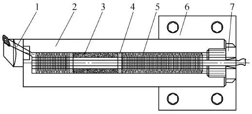
Figure 1-21 Schematic diagram of the structure of the vibration reduction tool device
1—machine head 2 one knife specific 3 one ball 4 one baffle plate 5 one disc spring 6—open knife seat 7—adjustment screw
Reasonable use of tools
The knife body 2 in the vibration-damping tool is made of high-speed steel W18Cr4V, with a quenching hardness of 58~62HRC. The knife body adopts a hollow tube. The structure of the hollow tube has good bending and torsional deformation resistance during the cutting process, and the wall thickness 20mm. The tool is ground after quenching on the outer circumference of the tool, and the tolerance is controlled within 0.03mm; the inner hole is reamed before quenching, and the dimensional tolerance is controlled within 0.05mm.
The inner hole of the tool is equipped with the ability to eliminate vibration and resist deformation The disc spring 5 and the ball 3 that eliminates vibration of various frequencies are separated by a baffle 4; the adjusting screw 7 is installed at one end of the cutter body to adjust the length and elastic force of the disc spring to adapt to different materials and cutting. force-sized workpiece. The tool body is integrally fixed on the open tool holder 6 for fixing on the tool table of the CNC machine tool. The machine head 1 is closely matched with the other end of the cutter body through the serrated V-shaped groove, and is pressed with screws to be tightly fixed. A cooling tube is installed in the tool body, and the high-pressure cutting fluid is poured into the cutting tool tip through the cooling hole to cool the tool and the workpiece, and the disc springs and the balls are staggered.
For finishing, the tool nose arc R0.2mm is generally used. The machining tools for key parts should be reasonably arranged, and multi-tool stepped cutting should be adopted, and roughing and finishing should be separated. That is, the tool used in the last pass should be used separately from the tools used in the previous steps to ensure the final machining quality.
The machining allowance is 0.5~1mm in the diameter direction, the end face of the inner hole is 0.2~0.5mm, the number of cutting tables is: cutting speed vc=300~380m/min, feed rate f=0.05~0.1mm/r
| Let's Start A New Project Today |
| Get a Free Quote |
Completion inspection
The detection of general dimensions should use general measuring tools as much as possible. For the detection of accuracy and key dimensions, special measuring tools, such as three-coordinate measuring instruments, pneumatic measuring instruments or comparators, can be used.
For the geometric tolerance detection with high precision requirements, in order to objectively reflect the actual status of the parts processing, in-machine measurement is allowed, that is, the tooling and clamping parts used for processing are used on the original processing equipment for acceptance.
Beneficial effects: In the CNC machining project, this operation method ensures the machining accuracy of the precision thin-walled aluminum tube parts. In different processing stages, by using various fixtures, the positioning and clamping of the precision thin-walled aluminum tube parts is realized, which solves the problem. The problem of deformation of precision thin-walled aluminum cylinder parts under the action of clamping force in product production. It can process aluminum cylinders with a wall thickness of 3~6mm, the dimensional tolerance is within 0.05mm, and the shape and position tolerances can also be guaranteed within 0.05mm.
Tuofa CNC Machining believes that; this operation method is suitable for the processing of various precision thin-walled aluminum cylinders. It has high positioning accuracy, simple operation, and convenient loading and unloading of workpieces. The clamping force can act on the clamping workpiece evenly, and the clamping force can be adjusted according to different situations. It is suitable for the positioning and clamping of various thin-walled aluminum cylinders, with a wide processing range and strong applicability.
 Tel/WeChat:
  Email:
 Home
Home
 Innovation of Machining Method for Flat Deep Groove Parts


