Types of Holes in Engineering and Machining: Symbol, Use
 Sep 19,2024

In the manufacturing industry, many engineering operations involve the use of holes. It could be for stating the diameter or to put a mark on material to initiate the operation. Holes have many types in engineering like bore, drill hole or counterbore. These are represented by their symbols and could be confusing for the people who are new to engineering drawings. This article will provide a comprehensive guide on what are the different types of holes in engineering, their symbols and uses.
In this guide, we will explore the following types of holes commonly used in machining:
1. Countersink Holes
2. Tapped Holes
3. Threaded Holes
4. Through Holes
5. Blind Holes
6. Round Holes
7. Reamed Holes
What are Holes in Engineering?
In engineering, hole refers to a circular geometry produced by a rotating cutting tool. Hole can either be blind hole or a through hole. Blind hole is milled to a specified depth, and it does not pass through the thickness of material. A through hole pass thru the thickness of material and is a complete hole. Blind hole cannot be seen from the other side while a thru hole can be seen.
Definition of Holes in Engineering
In engineering, holes can be defined as a cavity drilled or milled into a material. The holes can be differed in diameter, shape, depth, size or even orientation. These all features have different effects on functionality and performance of the product.

What do you call hole for screw
Threaded hole is common term use for the holes that has screw thread. It is also known as bolt hole for fixing holes. Thread inserts another terminology is used for a screw thread in molding process.
What is called ot screw and hole in automotive engineering
Thread hole or tapped hole in which threads are created internally by tapping tool. This allows easy fastening in automotive engineering. Screws are classified in their shapes and function.
Hole sizes are specified by what?
In engineering drawings, holes are specified by a symbol 'Ø. Hole diameter and specified hole depth are shown on engineering drawings by this symbol.
Key Features to Consider When Creating Holes
There are few things to consider during hole creation
Depth Considerations
Holes are milled to a specified depth. Its bottom can either be flat or pointed if it is a blind hole. Furthermore, hole depth is entirely dependent on cutting tools length.
Diameter and Tolerance
The hole diameter depends on cutting tool length. The standard hole diameter is varied from 0.0019-3in. The standard size also includes letter, fractional, metric, and number sizes. The dimensional precision depends on the tolerance of the hole. Dimensional precision can be affected by the sharpness and vibration of the tool. Hole precision is also affected by the chips formation and their build up.
Surface Finish and Roughness
Surface roughness is used to determine the texture of surface. surface finishes and roughness are affected by many factors like spindle speed, feed rate and hole depth.
Different Types of Holes in Engineering
The different types od holes used in engineering are explained below:
Simple Hole
It is a cutout in a circular cross-section within the workpiece. It has constant hole diameter and can pass through the thickness of material.
Simple holes: a) through hole, b) blind hole
Simple Hole Symbol
On engineering drawing, the callout symbol is the ‘Ø’ diameter.
Use
These are employed for fastening and are ideal for holding temporary plastic fasteners. Bolts and screws can also be held to act assembly points.
In some assemblies, these are used to provide a passage for air or fluid. The alignment of multi-part assemblies can also become easy with simple holes.
Blind Hole
It is a cutout in material and does not pass thru the material thickness. It is drilled or milled to a specified depth and has one open end and the other close end.
Blind Hole Symbol
It is represented by symbol is its diameter ‘Ø’ and a depth symbol on engineering drawings.
Use
Blind holes are used to hide screws and fasteners. It is used to tap and thread in drilling. And it allows fittings and assembling.
Through Hole
A thru hole pass through the material. It has both ends opened.
Thru Hole Symbol
It is represented by the diameter symbol ‘Ø’ and a word ‘THRU’ on engineering drawings.
Use
It is used to pass the wires in housing, cases and parts. It allows air and liquid to flow. It can sustain stresses within the material.
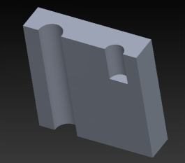
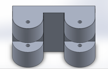
Interrupted Hole
This hole is the one that has an interruption by another feature. It can be another hole or part like extrusion. These are drilled or milled in a single sequence. The tool passes straight to the next part when there is no material.
Interrupted hole Symbol
There is no specified symbol for interrupted holes.
Use
This is used in complex and intricate geometry to thread for screws and bolts.
Counterbore Holes
It is a hole with a defined diameter and attached with a larger diameter hole above. The use of large holes is to hide the screw heads.
Counterbore Hole Callout
It is represented by the symbol ‘⌴’ on engineering drawings.
Use
It is used as a standard hole for screws readily available. It is used to save space instead of hex head bolt for socket head screws.
Countersink Holes
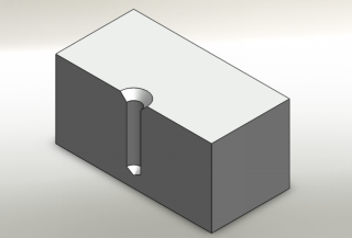
It is a simple hole and have a conical shape above it. This matches the angle and surface of the screw. In this way the screw fits and sit at the bottom of surface. countersink hole is opposite of the counterbore. Diameter precision is necessary to drill this hole.
Countersink Hole Callout
It is represented by the symbol ‘⌵’ on engineering drawing.
Use
It is used to place a countersink screw or bolt. Countersink holes allows the screw to stay at the bottom of surface.
Spotface Holes
In this hole, a specific area of material is faced. It is almost the same as counterbore hole, but it is shallow. The main difference between them is that this one has a flat surface, while the counterbore has shoulder type surface at the bottom.
Spotface Holes Symbol
It is represented by a counterbore symbol with the word “SF”.
Uset
This hole provides a flat and accurate surface. If product is made by casting, then this will not have smooth surface. Therefore, this hole is to make the surface right and is connected correctly and smoothly.
Counter Drill Holes
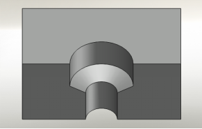
It has a conical shape with another hole above.
Counter drill Symbol
This has the same representation on engineering drawing as countersink hole or a counterbore.
Use
It provides seamless finish for bolts and fasteners. This allows space for a rubber seal between the fastener and workpiece.
Types of Holes in Machining
There are also different types of holes in the machining. These are as:
Tapered Holes
It changes its diameter as the hole progresses. It is narrow at the bottom of hole. Tapered holes are made by drill tip angle.
Symbol
It is represented by a triangle with a line passing through
Use
Tapered holes are used to press fit assemblies. It is used as tool holder due to conical shape.
Screw Clearance Holes
It allows bolt or screw to pass through easily. It has lager diameter than the screw shank.
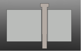
Callout symbol
Screw clearance hole is represented by the diameter symbol.
Use
It is used to pass bolt. In part assemblies, it is used to hold two parts using a bolt.
Tapped Holes
It has threads from top to bottom of holes. These threads are cut within the holes. The process to create a tapped hole is called tapping.
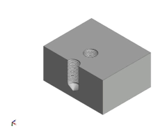
Tapped Hole Callout
It has different callouts and is according to standard bolts and screws.
Use
It is used to fasten the parts. It can hold screws and bolts and can join two parts.
Threaded Holes
Thread and tapped holes are mostly employed interchangeably. This one has screw threads cut into it by a taping tool.
Threaded Holes Symbol
The thread callout drawing is Metric Standard shown by an M is used to represent thread hole.
Use
It is used to hold bolts and screw thread assemblies. These are reusable and made for parts that require disassembling at any point.
Table of Hole Types and Symbols
Each type of hole is shown in table.
|
Type of holes |
Symbols |
|
Simple hole |
Ø |
|
Blind hole |
Ø |
|
Through hole |
Ø with a word ‘Thru” |
|
Counterbore hole |
⌴ |
|
Countersink hole |
⌵ |
|
Spotface hole |
⌴ with a word “SF” |
|
Threaded hole |
Metric Standard and an M |
|
Tapered hole |
triangle with a line passing through |
|
Tapped hole |
No specific symbol |
Common Hole Types with Their Symbols and Use
Cases
|
Type of holes |
Symbols |
Uses |
|
Simple hole |
Ø |
for fastening and are ideal for holding temporary plastic fasteners |
|
Blind hole |
Ø |
Blind holes are used to hide screws and fasteners |
|
Through hole |
Ø with a word ‘Thru” |
It is used to pass the wires in housing, cases and parts |
|
Counterbore hole |
⌴ |
It is used to save space |
|
Countersink hole |
⌵ |
It is used to place a countersink screw or bolt. |
|
Spotface hole |
⌴ with a word “SF” |
This hole provides a flat and accurate surface. |
|
Threaded hole |
Metric Standard and an M |
It is used to hold bolts and screw thread assemblies |
|
Tapered hole |
triangle with a line passing through |
Tapered holes are used to press fit assemblies |
|
Tapped hole |
No specific symbol |
It is used to fasten the parts |
Callouts and Engineering Drawings
The callout and engineering drawing of some common holes are as:
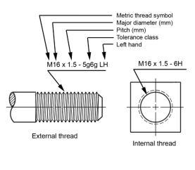
A) Threaded holes,
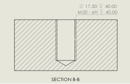
B) tapped holes
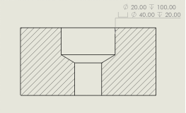
C) Counter drill hole
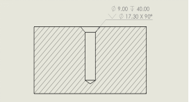
D) counter sink hole
How to Choose the Right Hole Type for Your Application
Material Considerations
Every material has different design approaches in hole drilling regarding the hole diameter and precision hole. This must be considered to avoid chips buildup, dimensional precision and depth ratios.
Machining Process Compatibility
Hole has the same geometry and diameter as does the cutting tool has. Most of the holes have same basics but different nature. This is because they all different purpose.
Cost and Time Efficiency
The cost and time efficient drilling are when the optimal penetration rate is achieved. This is done by selecting right bit for depth, pressure, temperature, and other parameters like bit life, rate of penetration (ROP), and overall performance.
How to Measure Holes Accurately in Machining
There are tools to measure holes accurately in machining as precision holes are necessary to drill.
Which tool is used primarily to cut holes in various types of material
Drill press is the commonly used tool to cut holes in different materials. because it provides precision holes as compared to hand tools. It is more ideal for complex parts that require dimensional precision.
Tools and Techniques for Depth and Diameter Measurement
The tools used to measure hole diameter and thickness are caliper gauges. For depth measurement, depth Caliper and depth Gauges are used. Depth micrometers are latest advancement in tools.
Best Practices for Maintaining Tolerance
Dimensional precision and tolerance depend on many factors such as workpiece material, forces applied, torque and power. These all must be selected with the requirements of the project.
Common Challenges in Hole Machining and How to Avoid Them
There are common challenges that occur in hole machining. These are as:
Dealing with Burrs
Burr is controlled by adjusting processing conditions, like feed rate and cut depth. Normally the higher feed rate increases the burr size. Secondary burrs are easy to remove.
Tolerance Issues
One of the common tolerance issues that occurs is Kick tolerance. The is the maximum amount of gas or liquid entering the bore without causing control issues and is safe during drilling. The exceeding amount from maximum value can cause tolerance issue in drilling.
Ensuring Roundness
Drilling is highly affected by parameters like spindle speed and feed rate to optimize the hole roundness. Low feed rate and spindle speeds are recommended to ensure quality drilling.
Comparison of different holes
Countersink vs Counterbore
Countersink hole has a conical shape matching with the angle of screw. Counterbore is used to enlarge the hole opening and has a flat bottom.
Blind hole vs Through hole
Blind hole has one close end and are milled to a specified depth. Thru holes can pass through the material and has both ends opened.
Tap drill vs Clearance drill
Tap drill is used to run a tap inside a hole and create threads in it. Clearance drill has a hole by which a bolt can slide through easily.
Tapped hole vs Threaded hole
Tapped holes have threads from top to bottom of holes and are reusable if the screws are to be removed at some point. Threads holes are permanent and has screw threads cut into it. The thread callout drawing is Metric Standard.
Frequently Asked Questions
What is a counter drill?
It has a conical shape with another hole above. It provides seamless finish for bolts and fasteners.
How to avoid misalignment when machining holes?
Misalignment can be avoided by utilizing a spotting drill and by selecting an appropriate material specific drill.
What is the typical tolerance for different hole types?
|
Holes |
Tolerance |
Diameter (mm) |
|
F8 |
+0.035-0.013 |
|
|
G7 |
+0.020-0.005 |
|
|
H7 |
+0.005-000 |
Conclusion
In engineering, holes can be defined as a cavity drilled or milled into a material. holes have different types in engineering and machining. Each serves a different purpose in engineering. these are like blind hole, thru hole, counterbore, countersink and spotface hole in engineering. Other holes are tapped holes, threaded and tapered holes. Low spindle speed and feed rate results in high dimensional precision to keep the hole diameter constant. Precision holes can be drilled or milled with tight tolerance and high accuracy by drill press.
 Tel/WeChat:
  Email:
 Home
Home
 Is CNC Machining Expensive? 9 Key Factors


