Tooling Design for Simultaneous Machining of Multiple Parts by CNC Lathe
 Nov 07,2022

Through the analysis of the process plan, a special fixture is designed to combine with the CNC lathe, and the CNC lathe is used to replace the original CNC milling process, which not only improves the processing efficiency, but also stabilizes the processing quality.
Order from University CNC Turning
In the process of school-enterprise cooperation, Tuofa CNC Machining, as an internship factory in Chinese universities, received orders for a batch of parts (see Figure 1) that required CNC turning processing. It is required to process two arc surfaces on the two wings of the workpiece. The two arc surfaces are rotated 180° relative to the axis of the workpiece, which are exactly the same. The tolerance of the arc R80mm is 0.057mm. The workpiece material is 45 steel, quenched and tempered, and the monthly output is 3,000 pieces.
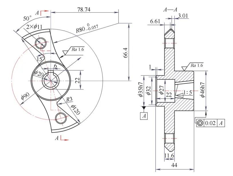
Figure 1 Parts
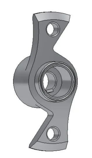
The original process route: rough and fine turning of each outer circle, step chamfer, inner hole and inner cone → drill two φ11mm through holes with a drill die → wire cutting processing of inner keyway → wire cutting processing of R3mm arc and two right angles Surface → CNC milling machine to process R80mm arc.
The R80mm arc is processed on the CNC milling machine, and the simple tooling originally designed uses a tapered mandrel with a taper of 1:5 and a diamond pin for positioning. The workpiece can only be processed individually. Although the processing accuracy can meet the design requirements, the processing efficiency is low, the processing cost is high, and the high-efficiency advantages of the CNC milling machine cannot be fully utilized.
After processing a batch of parts, Tuofa CNC Machining decided to redesign the processing plan and seek the feasibility of processing R80mm arcs on CNC lathes, replacing milling with turning, improving production efficiency, reducing production costs, and maximizing machine tool expansion. scope of use.
Processing technology of workpiece and design of special fixture
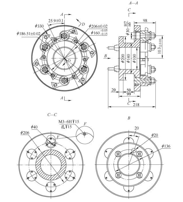
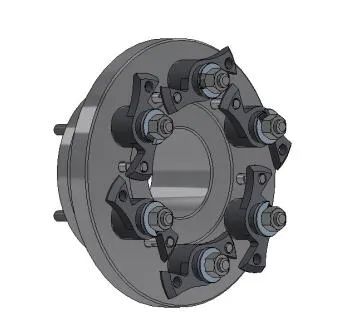
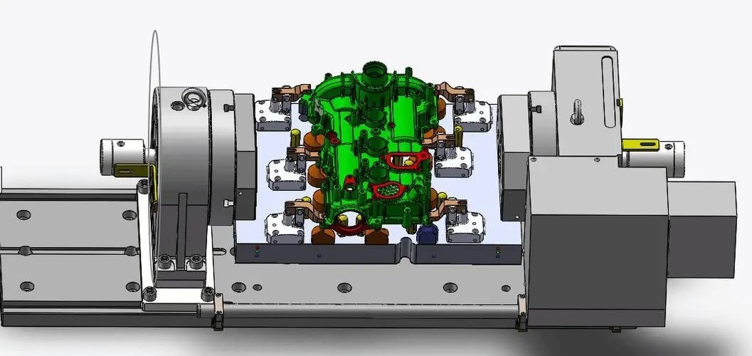
According to the structural characteristics of the parts, the process analysis was carried out again. The R80mm arc is a regular arc, as long as the center of the circle can be found and coincides with the rotation center of the lathe, it can be processed by the lathe. Compared with milling, the production efficiency will be greatly improved, so our engineering team designed a fixture that can be used on an economical CNC lathe and can clamp multiple parts at the same time, as shown in Figure 2.
Figure 2 Fixture
Processing technology of workpiece after applying new tooling
1) Roughly and finely turn each outer circular step chamfer, inner hole and inner taper hole on the CNC lathe.
2) On the drilling machine, use the drill die to position and drill two φ11H8 through holes on the plane (the machining accuracy of the holes needs to be properly improved for positioning).
3) The keyway on the inner cone surface is processed by wire cutting. First, before cutting the inner taper part, try to cut a punch part of the same height, and record the current ZSD\ZID\Z0 value; secondly, measure the actual angle and actual size of the test piece, and calculate the correction value; finally, cut the tapered part, The obtained measured dimensions and angle values are relatively accurate and meet the design requirements.
4) CNC wire cutting process R3mm arc and two right-angle surfaces.
5) Use the newly designed special fixture on the CNC lathe, and use the 1:5 inner tapered hole as the positioning reference (because the positioning reference has been converted, the coaxiality between the tapered hole and the design reference should be ensured in the processing of the previous process), Process R80mm arc surface. At this time, the machining of the R80mm arc surface has actually been transformed into turning a φ160mm hole.
The structure and working principle of the fixture
The fixture mainly includes a clamping body, a tapered mandrel, a diamond pin and a pressing element [1]. After installation, let the R80mm arc surface of the workpiece be distributed on the circle with the center of rotation of the lathe spindle as the center and the radius of 80mm, as shown in Figure 3 and Figure 4.
1—Tapered mandrel 2—Workpiece 3—Washer 4—Nut 5—Rhombus pin
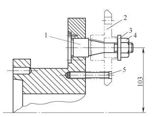
Figure 3 Workpiece clamping
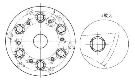
Figure 4 Workpiece clamping layout
On the circumference of the clamp body with a diameter of 160mm, install as many positioning mandrels and diamond pins as possible according to the size of the workpiece, and strive to ensure that the workpieces do not interfere with each other and make full use of the space. Any one of the φ11H8 holes drilled on the workpiece is used for anti-rotation positioning, so that multiple workpieces can be processed at the same time.
Positioning analysis of workpiece in fixture
The workpiece is installed on the clamping body, the tapered mandrel limits the workpiece's 5 degrees of freedom, and the diamond-shaped pin limits 1 rotational freedom, which is equivalent to positioning with two pins on one side. The six degrees of freedom of the workpiece are completely restricted, which belongs to complete positioning, and the positioning is safe and reliable [1, 2], as shown in Figure 5.
Figure 5 Workpiece positioning
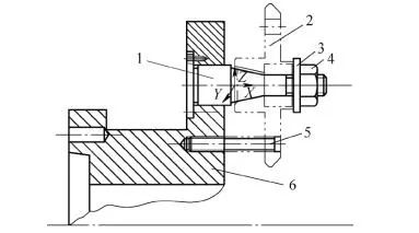
1—Tapered mandrel 2—Workpiece 3—Washer 4—Nut 5—Rhombus pin 6—Clamp body
Fixture main components
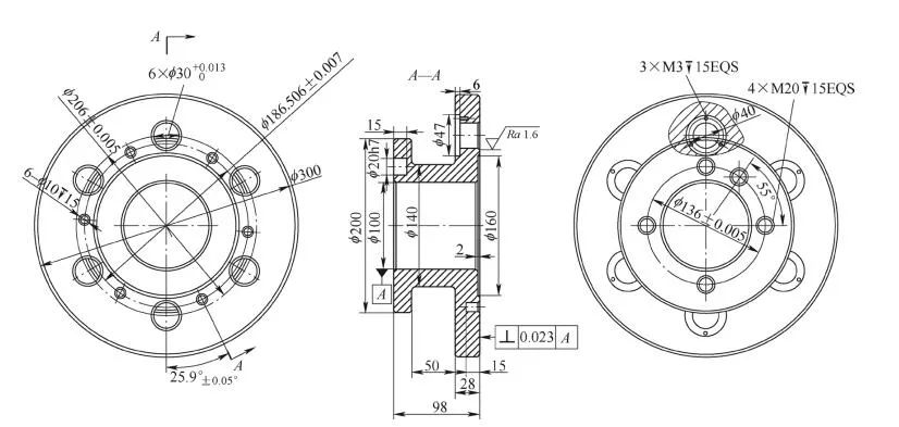
1) Clamp body As shown in Figure 6, the size of the flange connecting the clamp body to the machine tool should be prepared according to the size of the spindle end of the machine tool. The circumference size of the 6 holes for installing the positioning mandrel and the position of the holes for installing the 6 diamond pins should be determined after accurate calculation according to the radius size and position requirements of the machining arc .
Figure 6 Clamp body
2) Tapered mandrel as shown in Figure 7.
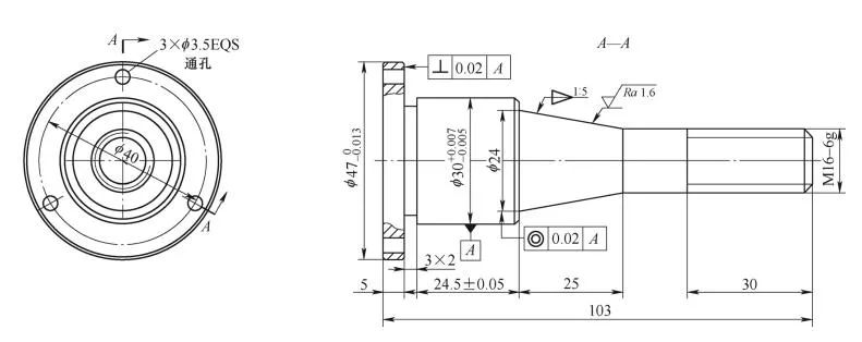
Figure 7 Tapered mandrel
3) Diamond-shaped pin As shown in Figure 8, the diamond-shaped pin is matched with the positioning hole of the workpiece with a small gap, which not only ensures the convenient installation, but also limits the rotation of the workpiece as small as possible. The assembly of the diamond pin and the clamp body adopts the interference fit of φ10H7/n6 to ensure that the diamond pin is firmly fixed on the clamp body. It should be noted that when the diamond pin is installed on the clamping body, the narrow surface of the diamond pin should be perpendicular to the line connecting the center of the diamond pin and the center of the tapered hole of the workpiece.
Figure 8 Diamond pin

How to use the jig
Install the fixture on the machine tool spindle and check the correctness of its installation with a dial indicator.
After completing the relevant procedures, the workpiece is installed on the clamping body and pressed with a nut, and then the R80mm arc surface can be turned [3, 4]. The process is: ① rough turning the workpiece φ160mm hole, leaving 1mm finishing allowance. ②Fine turning workpiece φ160mm hole to tolerance requirements.
After the processing is completed, remove the workpiece, rotate the workpiece 180° and re-install it, and then the R80mm arc surface on the other side of the workpiece can be processed.
Due to the simultaneous installation of multiple pieces of processing at one time, the idle stroke of the tool is reduced, the effective cutting time is increased, and the processing efficiency is significantly improved. High-speed steel tools are used for processing on CNC milling machines, and carbide tools are used on CNC lathes. Since the cutting parameters of carbide tools are much higher than those of high-speed steel tools, the use of this fixture not only improves cutting efficiency, but also improves cutting efficiency. The tool cost is also reduced, and the comprehensive economic benefit is significantly improved.
Tuofa CNC Machining innovation process to cope with the changes of the times
In the design of mechanical parts, the arc surface is often used, and the processing technology of the arc surface is various, and different processing technology should be adopted according to the arc curvature, material and technical requirements. Because different processing techniques will inevitably produce different processing effects, the technicians must fully demonstrate various process schemes when compiling the processing techniques.
The traditional process is certainly feasible, but with the advancement of science and technology, a large number of new equipment and new tool materials have emerged, and process designers must also keep pace with the times, develop CNC machining to break through traditional processes, adopt optimal solutions, and achieve Maximize economic benefits. Through the practice of this paper, it is proved that it is completely possible to use economical CNC lathes and reasonable process equipment to realize milling instead of turning and simultaneous processing of multiple pieces.
The fixture is simple in structure, convenient in manufacture, and has certain universality, and has certain reference significance for the processing of arc elements on special parts.
 Tel/WeChat:
  Email:
 Home
Home
 World-class CNC Competition, China's Youth CNC Turning and Milling King!


